
 |
GDSII Output |
|
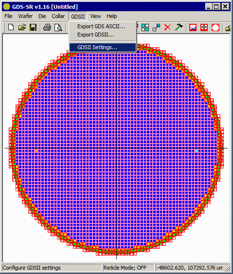
Once the die has been arrayed and any knockouts, deletions and substitutions completed, the user will want to export a GDSII file for the mask. Prior to exporting the GDSII, the user will want to check the configuration settings where layer control is possible. Use the GDSII pulldown and select GDSII Settings ... to open the GDSII settings dialog. |
|
|
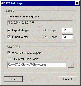
At the top of the dialog a bar shows the layers that were found in the imported die. The data on these layers will be included in the GDSII output. Export Margin - if you would like the margin boundary to be exported to a layer, check this box and specify the layer. Export Wafer - if you would like the wafer boundary to be exported to a layer, check this box and specify the layer. |
|
|
|
View GDSII - if you would like the GDS-SR program to automatically launch a GDSII viewer and to pass it the gdsii file name, check this box and enter the path/executable name of the gdsii viewer. |
||
|
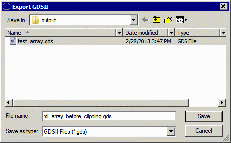
Exporting the GDSII File Click on Export GDSII... from the GDSII pulldown. This will open a dialog box where the file name and location are specified (the default directory is set in the prefernces ...) |
|
|
Here is a snapshot of the wafer mask (before clipping) 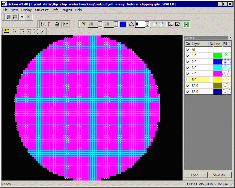
|
||
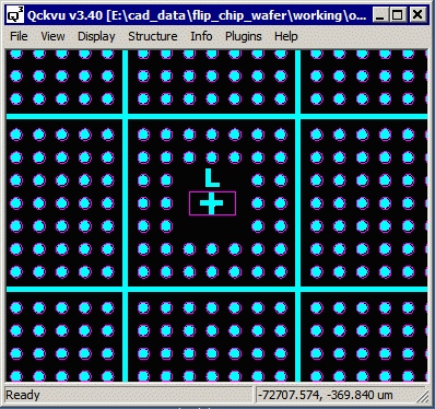
| Zoom in view of the left target. You can see that that the unit die has been correctly replaced. |
|
|
Next Up - SINF Output |
||
| Program Operation: 1 2 3 4 5 6 7 8 |
| GDS-SR Home | Download | Revision History | Price |