

|
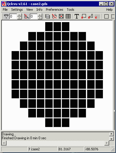
Case 2
|
|
||
Command LineThe command line is all one line -- it is shown here broken into several lines for purposes of clarity.
c:\wcad\collar\collar.exe

   case2.gds case2 1

        -bbox: -100,-100,100,100

          -cutout:-82,-82,-78,-78
          -cutout:78,-82,82,-78
          -cutout:-82,78,-78,82
          -cutout:60.0,91.0,96.0,95.0

             -margin:2
             -gap:2

                -output:collar2.gds,collar,6
|
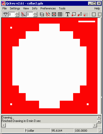
ResultsThe results are a GDSII file that has a collar on layer 6. The user can then merge this data with the array data (and targets/maskid) to produce the final wafer mask. FilesIf you would like to examine the sample files you can contact us and we will send them to you. |
|
||
Merging the Array Data and the Collar into a Single FileNow that we have a collar for the mask, the next logical step is to combine the array data and the collar file into a single GDSII file. This can be done using Artwork's GDSFILT program. Since this example is using a command line approach, we provide the command line to do this. GDSFILT Syntax
gdsfilte.exe

    input_file  output_file  input_file_top_structure

      -unixcmdline

         -add file1

           -combine output_top_structure  file1_structure


where
-----

gdsfilte.exe                 name of the gdsfilt engine

input_file                   one of the files to merge

output_file                  the new gdsii file that will
                             contain the merged data

input_file_top_strcture      top level structure of the input file


-unixcmdline                 a special argument (needed only in windows)
                             that tells the engine we are going to run
                             from a command line ...

-add file1                   names of file to add

-combine                     indicates we will combine the two files
                             and not replace any structure data; i.e. if
                             the files have common named structures they
                             will be renamed to avoid collisions

output_top_structure         the name of the top level structure in the
                             output file.

file1_top_structure          the name of the top level structure in the
                             file that will be added to the input file.
In our example the input file is called array.gds with a top structure name of array. The file to add is called collar.gds with a top level structure called collar. The output file will be called mask.gds with a top level structure called TOP.
gdsfilte.exe

    case2.gds  mask2.gds  case2

      -unixcmdline

         -add collar2.gds

           -combine TOP  collar
The results of merging the two files are shown below. The collar data (on layer 6 ) is displayed in red and the array data (on layer 1) is displayed in black. 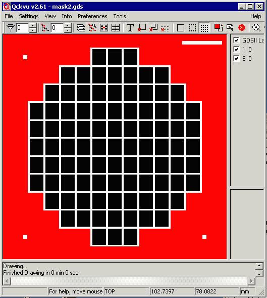
|
|
To make this example more interesting and complete, we are also going to place an alignment target in three locations (outside the array) as well as a mask id. The alignment target was drawn separately as was the mask ID. |
||
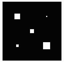 align.gds |
 mask_id.gds |
|
|
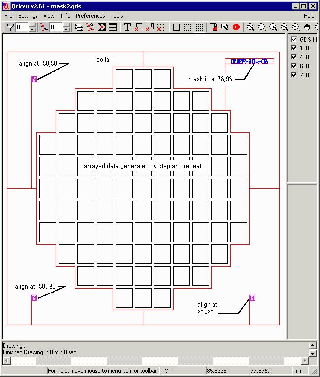
We need to insert the mask_id at coordinates: 78,93 and the alignment target in three locations: -80,-80, -80,80 and 80,-80. This means that we have to reference the align.gds file three times in the comand line. We need to add the -offset argument which controls the placement of each cell in the additive process. (We didn't need the offset command in the first part of the merging example because both files were placed at 0,0) The command line shown below is broken into sections for clarity. The GDSFILTE Command Line
c:\wcad\gdsfilt\gdsfilte.exe

     case2.gds mask2.gds case2

       -unixcmdline

              -add            collar2.gds mask_id.gds align.gds align.gds align.gds

              -combine  TOP   collar         TOP         TOP       TOP       TOP

              -offset   0,0    0,0          78,93     -80,-80    -80,80     80,-80
The Complete MaskThe completed mask includes: the arrayed circuits, the collar, three alignment marks and the mask id. Screenshots are shown below: 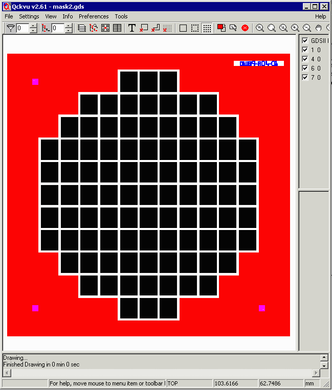
If you would like to examine the resulting files here they are for downloading: align.gds 2KB GDSII File mask_id.gds 6KB GDSII File mask2.gds 15KB GDSII File |
||
| Program Operation | Download | Revision History | Price |
|
|