

Extract 3D enables a user to define a rectangular region in GDSII to convert to a 3D model. Layers are assigned a vertical "thickness" and the program extrudes geometries on each layer to the specified thickness. The user also defines the order in which the layers are stacked up.
The 3D output is in Artwork's 3DI format which can then be exported to STEP or parasolids using our 3DVU program. STEP files are supported by simulation tools such as Ansys, ProEngineer, Comsol and others. Parasolids is especially good for import to SolidWorks.
The user defines a vertical stackup by assigning to relevant GDSII layers:
Additional Functionality
Because 3D files are larger and more complicated than 2D, the plug-in will check to see how many polygons and vertices the user has requested. If the number seems too high, the plug-in will report to the user the number of polygons/vertices and warn the user. The user may choose to continue or cancel the operation. The number of polygons/vertices that trigger a warning can be set from a resource file.
The plugin will (optionally) launch Artwork's 3DVU program.
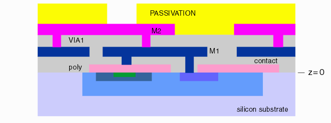
We define the following layer types and model them by a simple extrusion in the Z axis:
DIFFUSION - a layer whose top begins at the device surface and which is extruded downward. Diffusion layers do not "stack" up. Each diffusion layer always starts at the silicon surface and diffuses down.

POLY - the polysilicon layer which has as its bottom reference point the surface of the silicon.

CONTACT - an opening layer between M1 and either POLY or the surface of the silicon device.

METAL - the various metal layers (M1, M2, M3 ...) that are deposited after POLY.

VIA - an opening layer for vias between metal layers.

PASSIVATION - an opening style layer (similar to via) but instead of rendering the metal in the openings, the dielectric is rendered with holes in it.
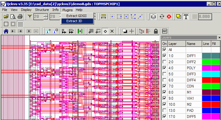
The user should first open the GDSII file in Qckvu3 and either define the appropriate process layers or load a technology file that maps the GDSII layer numbers to process layers such as M1, M2, POLY, CONTACT ... Then from the pulldown start the Extract 3D plugin.
Layers to be extracted must also be turned "on" for display.
Defining the Stackup
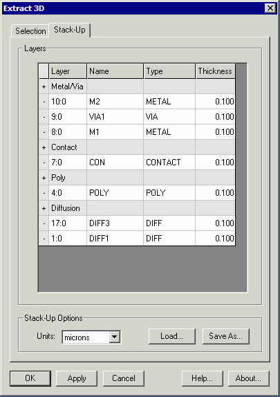
The Extract3D dialog contains two tabs - one for selecting the region to extract and a second for defining the stackup. To view a short video of how to add layers to the stackup click here.
Stackup Controls
+ - click on the + sign to add a layer of the given type ...
Layer - the GDSII layer:datatype is selectable using a pulldown
Name - picked up from the Layer Table
Type - use the pulldown to select the correct layer type if more than one is available (i.e. Metal/Via)
Thickness - enter the thickness of the layer.
Units - select the units for your thickness setting: microns, nanometers or angstroms.
Load - loads a stackup table from disk
Save As ... saves the stackup table to disk
Defining the Region to Extract
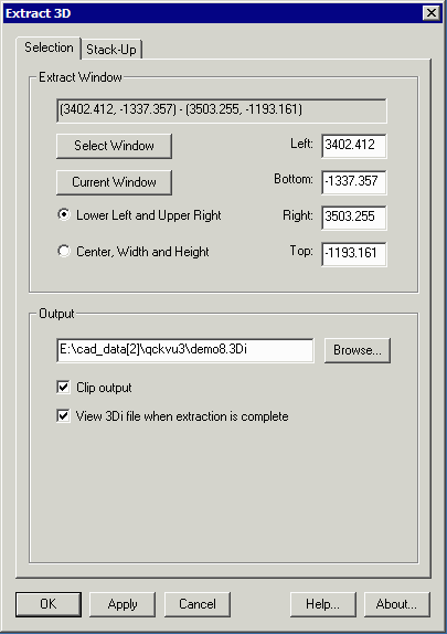
The Selection tab is used to define the region to extract. The user has multiple ways of defining this rectangular region:
Selection Controls
Select Window - clicking on this button will shift focus to the Qckvu3 display. Use the mouse to define the window to extract. The resulting coordinates will be returned to the dialog.
Current Window - clicking on this button will use the coordinates of the current display window. It is the user's responsbility to make sure that the window does not contain too many geometries to successfully export to 3D.
Lower Left and Upper Right - displays (and allows the user to edit) the coordinates based on the lower left and upper right corners of the rectangle.
Center, Width and Height - displays (and allows the user to edit) the coordinates based on the center coordinate of the window, the window's width and the window's height.
Output
File - the output file defaults to the GDSII name appended with the suffix .3di and will be written into the same directory as the GDSII file was read from. You can change this with the Browse button.
Clip Output - clips any elements that cross the selection windows. If not checked, elements that cross the window will be retained in their entirety.
View 3Di ... - when selected, automatically launches the 3DVU program and passes it the 3DI file.
Creating the 3D Output
Once the stackup is set and the window to extract has been defined, click either Apply or OK to create the 3D output (Apply leaves the 3D Extract dialog open - OK closes it ...)
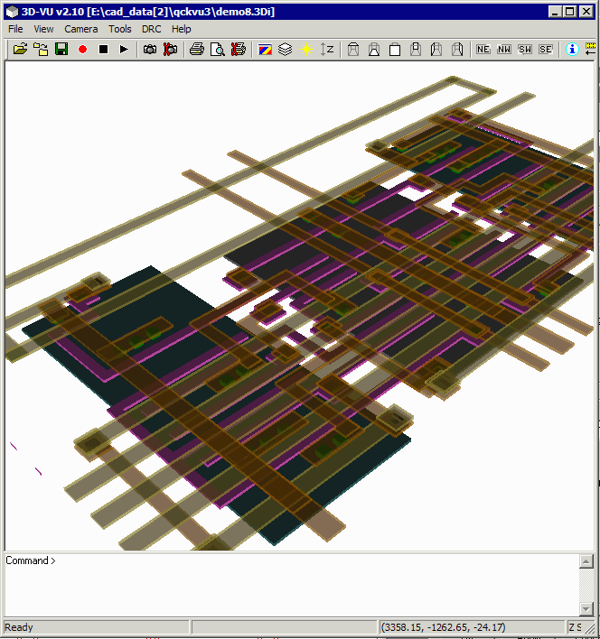
The results will look something like this:
The Stackup Table
The stackup table is an ascii file that can be saved by the Extract 3D plugin or read into the plugin. A sample is shown below:
# STACK-UP file written by Extract 3D v1.01

METAL
# Order Layerno Name     Type Thickness RGBA
  1     4:0     POLY     P    0.100000
  2     7:0     CON      C    0.100000
  3     8:0     M1       M    0.100000
  4     9:0     VIA1     V    0.100000
  5     10:0    M2       M    0.100000
ENDMETAL

DIFFUSION
# Order Layerno Name     Type Thickness RGBA
  1     1:0     DIFF1    D    0.100000
  2     17:0    DIFF3    D    0.100000
ENDDIFFUSION

UNITS
microns
ENDUNITS