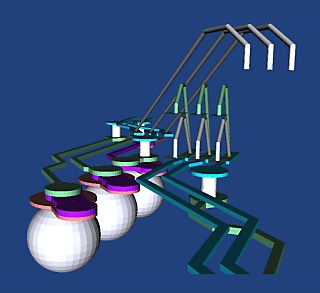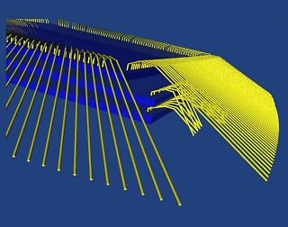

3DVU is 3D modeler, viewer and design rule checker intended for IC package designers. It reads a new database called 3Di which defines the package both in terms of geometries but also includes useful properties such as nets, material and package/pin information.
The 3D database is produced by extruding conductors and substrate information derived from two dimensional PCB layout tools. 3D wires are generated by using the 2D coordinates and applying a Z model to create an accurate representation of the wire's sweep. Nets, package and pin information are extracted from the PCB's layout database

In addition to the two basic JEDEC wire models, 3DVU supports user defined custom wire models.
This allows both designers and assembly engineers to more accurately model the extreme wire profiles needed today for stacked die.

In addition to viewing, 3DVU includes a DRC module. This DRC does in three dimensions what conventional tools do in two dimensions. Wire to Wire spacing, Wire to Substrate and Wire to Metal spacing can be measured and flagged if out of spec.
An optional plug-in, 3Di2STEP, can convert the 3Di data into the STEP database This enables the user to transfer 3D data to a wide range of 3D mechanical tools such as AutoDesk Inventor and ProE. Artwork's new parasolid output is ideal for tools such as SolidWorks and Ansys Workbench that uses the parasolid modeling kernel.
3D Net and Object Highlighting
3DVU can highlight a complete net of all connected conductors. The user can also highlight multiple nets such as differential pairs. This makes it fast to trace a connection from the top of a package to the bottom. The pins and net name are associated with the highlighted net are displayed.
Object Extraction
It is possible to use the multiple selection option (either by net or by object) to select a subset of the entire database and then save it as a new, smaller database. This can be very helpful for our simulation clients who want to limit the amount of data to simulate.