
The 3Di2XT (3Di to parasolid) was developed to speed up the importation of large data sets into programs such as SolidWorks that use the parasolid modeling engine as their kernel.

Artwork's STEP output can be imported into SolidWorks but the speed at which large files are imported is quite slow and as PCBs and packages get larger and more complex, the import speed became a critical bottleneck.
Artwork also has a direct API based importer for SolidWorks but this approach also suffers from the same speed issues when importing a large number of solid bodies into the same part.
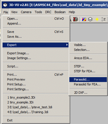
Most users will create the parasolids file from within 3DVU. To do this first use the File | Export pull down and select either the menu item:
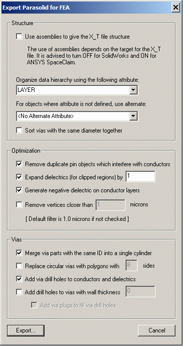
We are going to document the more complex of the two dialogs -

The dialog box for exporting parasolids will now appear. There are a considerable number of parameters and we explain what each one does below:
Structure
There are a number of ways to organize the output data. In almost every case, we want the parasolids file organized by LAYER. If you organize by a different attribute (such as NET) then you will want to specify a secondary sort parameter as not all entities have a net assigned to them.
Use assemblies ...This is an option introduced specifically for users of SpaceClaim. It generates an assembly definition in the parasolids file because that is what SpaceClaim expects upon import. Other tools such as SolidWorks, create their own assembly.
Sort Vias with same diameter ...This special sort was found useful by some Ansys users who replaced the via 3D solid body with an equivalent 2D sheet which accurately models the current flow but which reduces the computations the simulator needs to do.

Optimization
There are a number of optimizations which 3Di2xt (the parasolid converter) can do to make the job of the simulator more efficient.
Remove Duplicate Pin ObjectsWhen 3Di is generated from an EDA database it often generates duplicate objects at the location of each pin -- one object comes from the copper layout data and a second object is generated by the insertion of the component foot print. Checking this box will remove the extra pad or conductor placed when the component footprint is placed.
This directive is normally required when generating what we call "negative" dielectric - i.e. dielectric in the empty spaces between traces or pads on a conductor layer. In order to compute the solid bodies for this dielectric, we need to perform a Boolean between the board outline and the conductor bodies on each conductor layer. However where the conductor bodies touch the edge of the board outline, it is possible to generate tiny slivers that would cause the Boolean to crash.
To avoid such slivers, the program will "expand" the original board outline (which defines the extents of the dielectric) by a very small amount. the user can specify this amount.
This directive tells the converter to create dielectric in the empty spaces between traces or pads on a conductor layer. In order to compute the solid bodies for this dielectric, we need to perform a Boolean between the board outline and the conductor bodies on each conductor layer.
Most simulators and meshers need this dielectric - if it is not generated then there will be air gaps between traces on each conductor layer; not only does this not accurately represent a multi-layer PCB but it can cause simulators to fail at the transition faces.
If you do select this directive, you must also check Expand Dielectrics ... to insure the computation goes correctly.
This directive tells the converter to examine the 2D data that will be extruded into 3D, and to filter out any closely spaced vertices.
Not only does this reduce the 3D file size, but many meshers or simulators will fail if there are vertices with extremely small spaces between them.
Vias
There are a number of operations that the 3Di2xt export engine can do with vias that interconnect conductor layers in a PCB.
Usually vias appear in 3Di format as a series of stacked cylinders. Each cylinder runs from a condcutor layer to the layer below. Physically, vias can be treated as a single structure running from the top layer through intermediate layers to the bottom layer.
To achieve this in the 3D parasolid model, check this directive since all stacked vias share a common ID.
3Di knows a "via" is built from a round cylinder and will output it as an extruded circle. Some simulation tools don't digest this type of solidbody very well or at all. You can direct the converter to instead model the vias as an extruded polygon (user defined number of sides).
Since the vias are generated separately from the conductor and dielectric geometry, as they pass through conductors and dielectrics the via body "interferes" with the conductor pad and dielectric. By checking this directive, the program will generate a mating "hole" where the via passes through. This is an important feature to support most meshers and simulators.
Vias are modeled as solid cylinders. If you want the center of the via to be "empty" then check this directive. Do not specify the hole diameter - specify the wall thickness you want and the program will compute the needed hole diameter. This approach is good when you have vias of different diameters.
Note: there is no method to specify that some vias will have drill holes and others will not.
If you have selected the directive to add drill holes to vias then you can choose to have those holes filled with a cylinder (solid body) that would be used to simulate a solder plug.
Conversion from 3Di to parasolid can also be run using a command line for 3Di2xt for applications where one does not wish to launch the conversion from withing 3DVU.