Importing AIF Data into Qckvu3
With the AIF import plug-in, a user can import pin geometries defined by an AIF file into Qckvu3 and overlay those geometries against a GDSII file. This plug-in was developed to check netlist (AIF) vs layout for packages with hundreds or thousands of bumps. By running a Boolean operation against the two data sources one identify missing bumps.
Sample Exercise
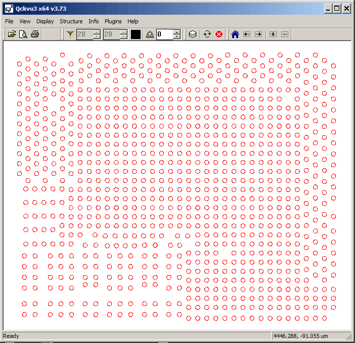
Suppose we've just completed the layout of a flip chip package. The screen shot below shows the bump openings on the top of our package. We want to verify that there are no missing or extra bumps on our package layout.

As an input to our package design we started with an AIF file of the IC. This file defines the die pad coordinates of the device along with the pin label and net name.
[DATABASE]
TYPE=AIF
VERSION=2.0
UNITS=UM

[DIE]
WIDTH=5050
HEIGHT=4200
CENTER=0,0
NAME=FLIPCHIP

[PADS]
BUMP135 = CIRCLE 135

[NETLIST]
;NETNAME  PAD# TYPE      PAD_X      PAD_Y

net1       2   BUMP135    259.40    1189.23
net2       5   BUMP135   -612.26    1601.07
net3       6   BUMP135  -1249.80    1463.63
net4      10   BUMP135  -1387.00    -182.77
net5      19   BUMP135  -1935.41     911.20
net6      21   BUMP135   1219.80    -594.37
net7      22   BUMP135    396.60    -594.37
The Import AIF plug-in imports an overlay of the AIF into Qckvu3 enabling the user to check the alignment between package and AIF. Then it will export a new GDSII file with both the package layer and the AIF layer -- plus performs an XOR operation on the two layers to provide a difference layer. By examining the difference layer one can easily find missing or extra bumps/pins and any misalgined pins.
Now we have two layout views
- The GDSII generated by the package designer
- The GDSII generated by importing the AIF file
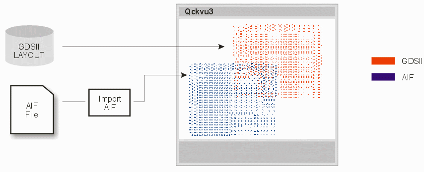
Here's the data flow:

Alignment Problems!
As you can see in the above flow diagram, the two layouts don't align! That means we really can't compare them to find any missing or extra bumps (pins). Why don't they line up?
Mirroring
If you zoom in and examine each layout, you will see that relative to the AIF layout, the GDSII layout is mirrored along the Y axis. This is not really surprising considering we are working with flip chips. So we will definitely have to mirror the GDSII data along the Y axis to get alignment.
X,Y Location
If you measure the extents of each layout, you will find that the AIF generated layout is centered about 0,0 but the package layout has its lower left corner at 0,0. We need to translate the package layout by the appropriate amount in X and Y to get alignment.
Scaling
Not so obvious, but the scale of the two layouts is slightly different. It turns out, that because of process related shrinkage, the package layout has a slightly different scale factor than the AIF layout. So a scale factor will have to be applied to the GDSII coordinates insure that both layouts can be properly aligned.
So, to get this accurate alignment the user will use the View | Transform dialog in Qckvu3 to modify the package layout to match the AIF layout.