Windows User Interface
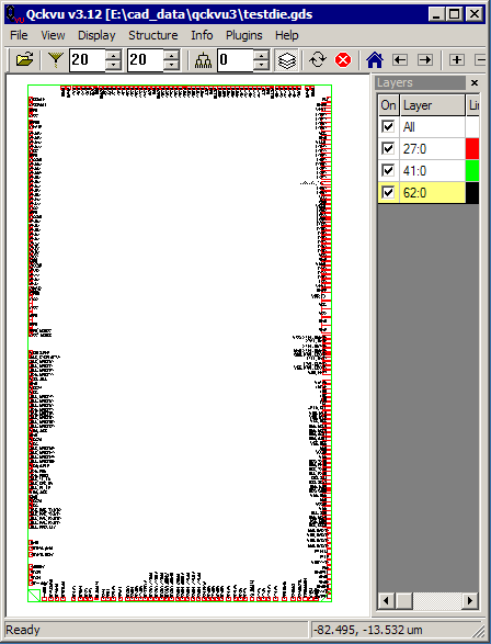
Open a File - Open a GDSII file using Qckvu3 and select the top level structure.
Layers -Make sure that the die pad opening layer (passivation) is turned on. If there is a separate text layer with net labels turn that on also. Do not try this with a full metal layer because too many objects on such a layer look like die pads. If all you have is a metal layer with millions of polygons you might need to run a filtering program such as DC2.
In the example there are three layers -- one has the die outline on it, one has the die pad openings and the third has text that labels the pads.
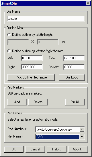
Open the Smart Die dialog by clicking on the Plugins drop down menu and selecting SmartDie ...
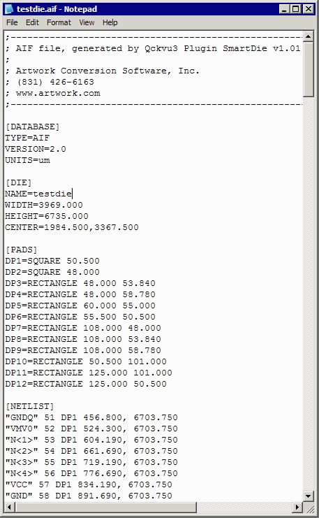
Die Name - Enter the name that you want to appear in the output table.
Outline Size - Sets the size of the die. There are several ways to do this
(a) If you know the die dimensions and the die is symmetric, you can enter the width and height into the field.
(b) If the outline is not symmetric about the extents of the die pads (some analog chips) then enter the lower left and upper right corner in the fields provided.
(c) If you wish to use the display to enter the coordinates first press the button labeled: Pick Outline Rectangle and then click on the vertex of an object to define one corner, pan to the other corner and click on another vertex. The coordinates will be transferred to the dialog box.
Die Logo - If there are geometries that form a die logo and you want to extract them to the AIF file, first click on the button labeled: Die Logo. Then using the mouse, window a region that contains these geometries. They will be highlighted.
Pad Markers - The SmartDie module will "mark" each die pad with an X. It will also display the number of die pads found. Assuming the count is correct and all die pads have an X in them you can continue. If the count is off, check to see whether an entity that is not a die pad has an X in it or an geometry which should be a die pad does not have an X. Use the Add/Delete button to add or remove entities from the pad count.
Pin #1 - In order to number the die pads it is necessary to specify which is pin #1. Press the button labeled Pin #1 and then use the mouse to select the desired pad.
Pad Labels
Pad Numbers - Generally, the pad numbers are generated automatically by selecting either Auto Counter Clockwise or Auto Clockwise. However if there is a text layer that has the pad numbers on it you could select that layer to use.
Net Names - If you have text that can be used to label the die pads, select the layer that that text is on. Note that the number of text strings must match the number of die pads.
If you do not have text strings, then select either clockwise or counter-clockwise.


