
In our documentation and examples we often use terms that either may not be familiar to our users, or which may have a different meaning to our users than we intend. This glossary is provided as a convenient location where we define such terms and, if appropriate, include some simple diagrams.
Definition - A convex boundary is one where if you draw a ray through it (along the X or Y axis) the ray crosses the boundary edge only once as it enters and once as it exits the boundary.
We can futher refine this definition into:
Convex in X - the ray passes through the boundary once parallel to the X axis.
Convex in Y - the ray passes through the boundary once parallel to the Y axis.

Definition - A vertex is the point where two edges of a boundary meet. A boundary is defined by listing its vertices in order either a clockwise or counterclockwise direction.
How Vertex Data is Stored
Bool.dll stores boundary vertex data as a pair of coordinates; the x and y vertex records are each 4 byte signed integers. Each vertex requires 8 bytes (2x4) to store in memory.

Note that a vertex pair record is required for both the first and last vertex on the boundary which means that there is one more vertex record in the database than there are physical vertices in the rendered boundary. e.g. a rectangle has 5 vertex pairs in the database but only 4 vertices when rendered.
Definition - Partitioning is a way of dividing up a large problem into multiple smaller ones. This is normally done to control the computation time as the input data set gets larger.
Notes
When using Bool.dll the programmer can choose to block any partitioning, allow the library to best determine partitioning or specify precisely how the data is to be partitioned.
When partitioning is used, the output boundaries may be "sliced" if they cross a partition boundary. The programmer can call a function to "repair" those slices, if desired.

Definition - Leonov is a term we use for a combination of boundaries where there is a single "parent" boundary who contains (fully surrounds) one or more child boundaries. This is named after the Russian mathematician, Michael Leonov, who wrote some seminal papers on Boolean operations for such sets.
Notes
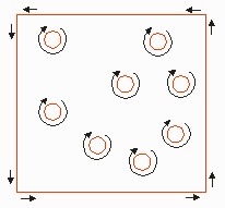
Whenever one must deal with a void inside of a boundary there is the issue as to how to represent this. On approach is to use a re-entrant polygon with cut lines. A second approach is to use Leonov polygons where each void is an independent boundary.
Bool.dll can write Leonov polygons and can read them. Some bool.dll functions do not support Leonov polygons.
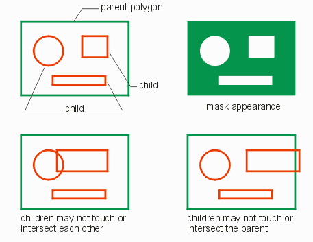
The parent boundary (polygon) must completely contain the children. The children may not touch the parent or other children.
Direction: this illustration implies that the parent must be drawn CCW and the children CW. There is no such requirement.
Definition - The parent polygon (or boundary) in a Leonov set is the outer one which contains all of the inner ones.
Notes
See Leonov and childDefinition - The child polygon (or boundary) in a Leonov set is completely contained or surrounded by the parent polygon. There can be multiple child polygons contained within a single parent. Child polygons may not touch or intersect each other nor may they touch or intersect with the parent.

Notes
See Leonov and parentDefinition - The winding rule is used in order to determine which regions are "filled" when processing a polygon tha self intersects. In the EDA world, it is important to be consistent with the CATS mask generation program which is used by a majority of the mask shops to convert databases such as GDSII and OASIS into mask writing commands. [True when this was originally written but not longer true as of the date of this revision - May 2024] CATS supports two options: ON and OFF which are illustrated below:
Consider this polygon(boundary) that self intersects. The vertices are labeled in order.
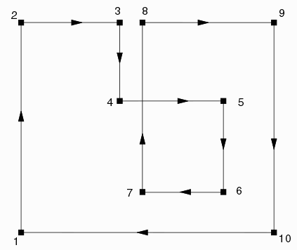
Winding Rule = ON
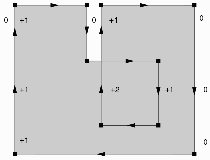
A scan line algorithm running from left to right is used to separate the interior from the exterior of the polygon. Each time the scan line crosses a vertical edge going upwards the rule count is incremented by +1. Each time the scan line crosses a vertical edge going down the rule count is adjusted by -1. Then we could label the regions as shown below:
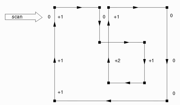
Now the rule (with option YES) says: any region with a non-zero value is defined as data.
So we should render the polygon as shown below:
Winding Rule = OFF
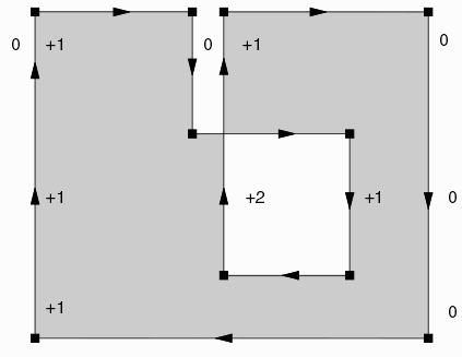
For the CATS winding rule = OFF option, we still increment or decrement the region value based on the vertical edge direction; however the rule now states:
Any region with even value = empty; regions with odd value = data.
Therefore we would render the polygon as shown below:
Definition - Manhattan geometry consists of all polygons/boundaries or paths whose edges are parallel to the X or Y axis.
Notes
Some IC layout tools or postprocessors still require that the input data be Manhattan as this allows one to greatly simplify various operations. Bool.dll has a flag for known Manhattan data - if the flag is set certain routines can be used that are much faster than the routines used to handle all angle data. However bool.dll has no requirement to use only Manhattan data.

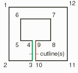
Definition - A cut line is a pair of edges that go "into" and "out of" a re-entrant polygon. A re-entrant polygon may have multiple sets of cut lines.
Notes
see Winding Rule and Re-Entrant Polygon
----------------------------------------------------------------------------------------
Definition - A re-entrant boundary is one that has one or more cut lines that define internal voids. This is also referred to by some as a "keyhole" boundary.

Definition - A Boundary in GDSII or OASIS is a closed area defined by a list of X,Y vertices connected by straight segments. Many CAD systems allow the boundary to self intersect but the early layout systems did not. The minimum number of vertices is 3. The maximum varies. Initially the original GDSII specification limited the maximum number of vertices to 200. However this proved to be a very small number and the structure of the GDSII database allows the maximum number of vertices to be as high as 8191. Every CAD system varies as to what is considered the maximun number of vertices so check on your target before setting the max value.
In general one should avoid pairs of vertices with 0 spacing. Vertices should not trace backwards over the previous vertex pair. This may cause the software or system receiving such data to throw an error.
Definition - a closed area defined by a list of X,Y vertices connected by straight segments. The terms boundary and polygon are often used interchangeably.
Definition - A Path is series of connected line segments with width defined by a list of X,Y coordinate pairs. The width of the path is constant. Generally, the path should not self-touch or self-intersect though nothing prevents the data from creating such a path. The original GDSII spec set the maximum number of vertex pairs per path to 200. However this limitation is likely no longer in force for virtually all CAD systems. The actual record structure of GDSII does limit the maximum number of vertex pairs to 8191.
An issue with the GDSII Path is how to treat the corners when the path bends through an angle of more than 90 degrees. The outer corner of the bend begins to extend outwards in a way not anticipated by the original definition.
Therefore, various CAD systems will attempt to "miter" the outer corner of such a bend. However there is no industry standard as to how to go about that miter.

Notes
see Endcap The Path Encap attribute defines how the beginning and end of the path appear in the CAD data.
Definition - A cut line is a pair of edges that go "into" and "out of" a re-entrant polygon. A re-entrant polygon may have multiple sets of cut lines.

Notes
see Winding Rule and Re-Entrant Polygon
Definition - A cut line is a pair of edges that go "into" and "out of" a re-entrant polygon. A re-entrant polygon may have multiple sets of cut lines.

Notes
see Winding Rule and Re-Entrant Polygon
Definition - A cut line is a pair of edges that go "into" and "out of" a re-entrant polygon. A re-entrant polygon may have multiple sets of cut lines.

Notes
see Winding Rule and Re-Entrant Polygon
Definition - A cut line is a pair of edges that go "into" and "out of" a re-entrant polygon. A re-entrant polygon may have multiple sets of cut lines.

Notes
see Winding Rule and Re-Entrant Polygon
Definition - A cut line is a pair of edges that go "into" and "out of" a re-entrant polygon. A re-entrant polygon may have multiple sets of cut lines.

Notes
see Winding Rule and Re-Entrant Polygon
Definition - A cut line is a pair of edges that go "into" and "out of" a re-entrant polygon. A re-entrant polygon may have multiple sets of cut lines.

Notes
see Winding Rule and Re-Entrant Polygon
Definition - A cut line is a pair of edges that go "into" and "out of" a re-entrant polygon. A re-entrant polygon may have multiple sets of cut lines.

Notes
see Winding Rule and Re-Entrant Polygon
Definition - A cut line is a pair of edges that go "into" and "out of" a re-entrant polygon. A re-entrant polygon may have multiple sets of cut lines.

Notes
see Winding Rule and Re-Entrant Polygon
Definition - A cut line is a pair of edges that go "into" and "out of" a re-entrant polygon. A re-entrant polygon may have multiple sets of cut lines.

Notes
see Winding Rule and Re-Entrant Polygon
Definition - A cut line is a pair of edges that go "into" and "out of" a re-entrant polygon. A re-entrant polygon may have multiple sets of cut lines.

Notes
see Winding Rule and Re-Entrant Polygon
Definition - A cut line is a pair of edges that go "into" and "out of" a re-entrant polygon. A re-entrant polygon may have multiple sets of cut lines.

Notes
see Winding Rule and Re-Entrant Polygon
Definition - A cut line is a pair of edges that go "into" and "out of" a re-entrant polygon. A re-entrant polygon may have multiple sets of cut lines.

Notes
see Winding Rule and Re-Entrant Polygon
Definition - A cut line is a pair of edges that go "into" and "out of" a re-entrant polygon. A re-entrant polygon may have multiple sets of cut lines.

Notes
see Winding Rule and Re-Entrant Polygon