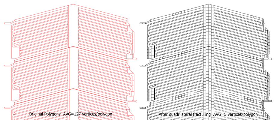
In order to increase the polygon density, we took a panel of the LCD2.GDS file and ran it through a special fracturing software that breaks the boundaries into small quadrilaterals. The mask pattern is the same. This fracturing software was developed for a laserwriter that could only handle quadrilateral data.
The net result is to greatly increase the polygon count. However, the polygons are much simpler and certain rasterizers can process these simple and small quadrilaterals extremely quickly. By running this file through QisMRaster we can see whether a high polygon count slows down the exploder.
You can see a detail of the out_l3.gds file below. Of course, the geometry is too dense to see any details at the full zoom level.

Left: original polygons; Right: out_l3.gds after fracturing. View Window: 575 um x 500 um.
For this test the area covered was 621mm x 1090 mm. The GDSII file, out_l3.gds was 200 MB in size. We processed Layer 30 which had been run through a proprietary fracturing software to increase the number of polygons. We used a tile (window) size of 5 x 5 mm with a pixel size = 0.315 um (81,500 DPI) This results in a bitmap of 16,000 x 16,000 pixels for each tile.
| Thread Allocation E x R | Number of Tiles | Total Clock Time | Avg Time per Tile | Image Size (pixels) | Image Buffer (MB) | Polys/Tile (Average) | Vertices/Tile (Average) | Vertices/Sec (Average) |
|---|---|---|---|---|---|---|---|---|
| 16x1 | 27,375 | 1,079 s | 39 ms | 16K x 16K | 32 | 176,360 | 881,709 | 22M |
1. The average number of polygons per tile is now 176K which is close to the client's description of his data.
2. On average, QisMRaster required 39 msec to complete each tile against a target of 100 msec. So it appears again to meet the required target -- even with this high polygon count file.
3. We can conclude that whether the layout consists of fewer large polygons with high vertex count, or many more small polygons within the tile, the overall throughput is not that different. This implies that the rasterizer will support efficiently both types of layouts.