SFGEN Reference
Preprocessing ODB++ and GDSII
for RIP with Real Time Correction

Copyright 2013-2017, Artwork Conversion Software, Inc.


Table of Contents

Distortion Correction

Transformation

Text Annotation


Distortion Correction

We are going to use a ODB++ test file called p1.tgz to illustrate how distortion correction is performed. Let's look at the layout and start with 4 reference coordinates located in the corners of the panel.
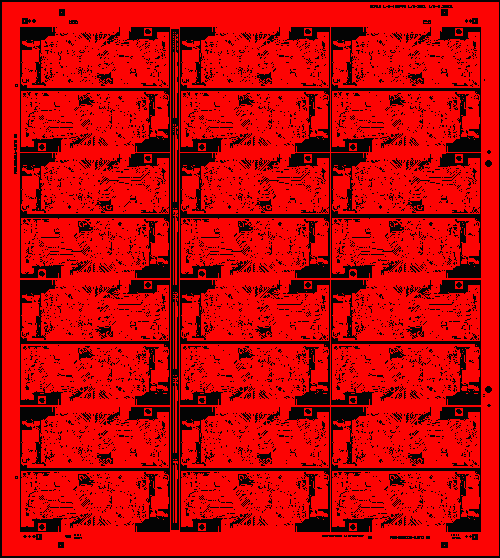
p51 full view of panel

If you zoom in on the corners you will see a small pad/drill hole (isolated from the ground plane so that the image acquisition system can find it and determine the precise coordinate. (dimensions shown are in mm)

We can use a CAD program to identify the CAD coordinates which are shown below:
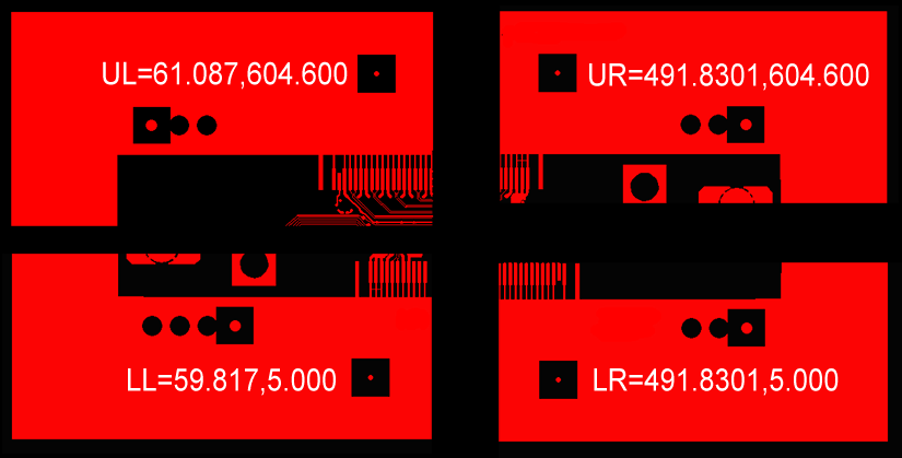
alignment mark coords from CAD

When the panel is loaded onto the imaging machine, a camera finds the same four targets and measures the coordinates precisely. In a perfect world, the measured coordinates would match the CAD coordinates. However, let's assume that the panel is distorted slightly due to some temperature related expansion that occured between drilling the holes and exposing the photoresist. Also, let's assume that because of the way the substrate is constructed, the expansion is not exactly the same in the X direction as the Y direction.

Let's assume that for this example the board expands by .25% along X and by .45% along Y. (We will stipulate that the expansion can be computed by using the center of the board as the scaling anchor point). In that case we find that the measured corners are found at:

Below you can see the movement due to expansion - where the CAD thinks the LL hole is located and where the camera system locates it.
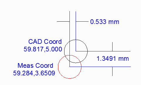
lower left distortion

Setting Up the Correction Table

Assuming you have located four targets and extracted the CAD coordinates and then measure the same targets on the substrate you can make a table such as the one below:

CoordLabel CADx CADy MEASx MEASy
LL 59.817 5.000 59.284 3.6509
UL 61.087 604.600 60.5572 605.9491
UR 491.8301 604.600 492.3772 605.9491
LR 491.8301 5.000 492.3772 3.6509

However the correction table requires that you enter the CAD coordinates followed by the delta to the measured coordinate. Further, it requires that the units be in microns. Therefore the table actually loaded into SFGEN will look like this:


59817,    5000,   -533.0, -1349.1
61087,    604600, -529.8,  1349.1
491830.1, 604600,  547.1,  1349.1
491830.1, 5000,    547.1, -1349.1

This is the file that should be loaded into SFGEN to correct distortion due to anisotropic expansion of the panel material.


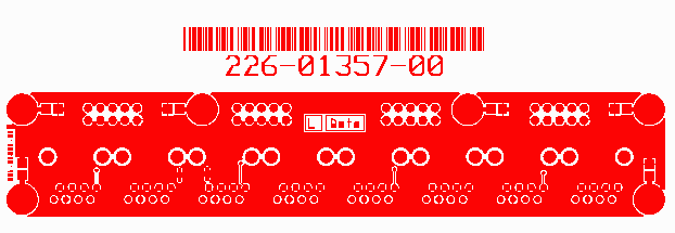

Text Annotation

The user may find it desirable to add some text at the time the SFGEN conversion is performed. This is usually associated with a mask ID, date code or lot number. SFGEN can read an annotation file which defines a string of text, bar code (optional) and location; it then creates the text polygons in the output file.

About the Annotation File

The annotation file can be produced by any application, manually or by a Qckvu3 Plug-in developed by Artwork. As long as the guidelines below are followed, text polygons will be produced.

Notes

    1. even though the input data can be in inches or mm, the text annotation box is always defined in mm.

    2. do not place a text box over "solid" metal as it will not show up.


B_TEXT_ANNOTATION                          <-- marks the beginning of a text annotation
HEIGHT      3.0				   <-- The text height in MM
XY          1.0 2.0			   <-- The text lower left insertion point in MM.
ROTATION 0                                 <-- text rotation in degrees (CCW) (not box rotation)
INVERSE NO                                 <-- if YES, means the text is "scratched" from the box
FRAME NO                                   <-- if YES, a line creates a frame around the text
MARGIN 0                                   <-- the distance between the frame and the top/bot/sides of the text
BARCODE NO                                 <-- If YES a 1D barcode is generated above the text  
HORZ_JUST L                                <-- not functional; can be ignored or deleted
VERT_JUST B                                <-- not functional; can be ignored or deleted
B_TEXT                                     <-- marks the beginning of one or more strings of text
ADDED TEXT FROM SFGEN                      <-- the string of text
E_TEXT                                     <-- marks the end of the string(s)
E_TEXT_ANNOTATION                          <-- marks the end of this text annotation


Examples with Snap Shots


Example 1

text annotation example 1
B_TEXT_ANNOTATION
HEIGHT      3.0
XY          32.2915 28.801
ROTATION 0
INVERSE NO
FRAME NO
MARGIN 0
BARCODE NO
B_TEXT
226-01357-00
E_TEXT
E_TEXT_ANNOTATION


Example 2

In example 2 we have two lines of text ...

text annotation example 2
B_TEXT_ANNOTATION
HEIGHT      3.0
XY          37.6661 29.9756
ROTATION 0
INVERSE NO
FRAME NO
MARGIN 0
BARCODE NO
B_TEXT
226-01357-00
Revision A
E_TEXT
E_TEXT_ANNOTATION


Example 3

In example 3 we typed in a line of text and requested a bar code to go with it

text annotation example 3
B_TEXT_ANNOTATION
HEIGHT      3.0
XY          37.6661 29.9756
ROTATION 0
INVERSE NO
FRAME NO
MARGIN 0
BARCODE YES
B_TEXT
226-01357-00
E_TEXT
E_TEXT_ANNOTATION


Adding Annotation from the Command line.

User can also add annotation from the command line using the executable addannotation64.exe located in the install folder.

addannotation64.exe input.gds annotation_file.txt output.gds -wdir:working_dir -log:logfile