SFGEN ReferenceTransformationsTransformations may be applied to the input data (ODB++ or GDSII) ScaleMirror Rotation Shift Offset (Edge Bias) |
The transformations are performed in the following order:
1 Scaling
2 Mirror X
3 Mirror Y
4 Rotation
5 Translation (Shift)
all units are in microns except rotation which is in degrees
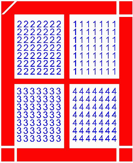
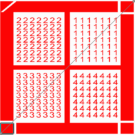
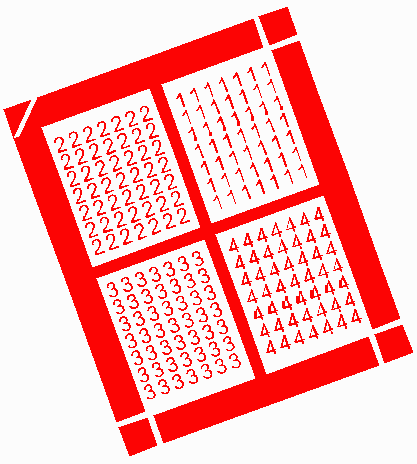
Test DataFor purposes of illustrating each transformation we will use the test file shown below. The extents are 500,000 um X 610,000 um and the data is centered at 0,0. It consists of "frame boundaries" on layer 1 and cells (1,2,3,4) with data on layer 2. No transformations |
ScalingScaling can be independently applied in both X and Y and the anchor point for scaling can be specified by the user. In the example below a scale factor of 1.1 has been applied in X and 0.9 in Y with anchor at 0,0. In most practical cases, only very small scale factors are applied in order to account for substrate expansion or contraction. Xscale=1.1,Yscale=0.9; extents are now 550,000 x 549,000 um. |
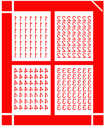
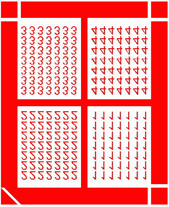
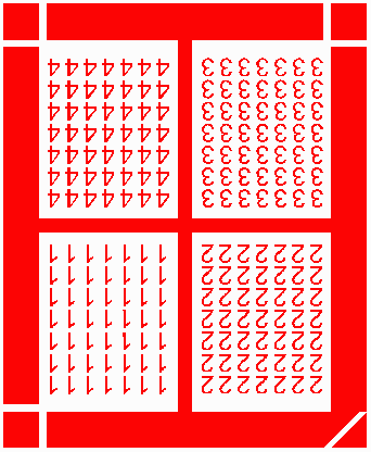
MirrorThe input data can be mirrored in X (about the Y axis), or mirrored in Y (about the X axis) or both. The position of the mirror line can be set. MirrorX (about the Y axis at X=0) MirrorY (about the X axis at Y=0) MirrorX and MirrorY |
RotationThe input data can be rotated around any user specified anchor point. Postive values of rotation move the data in the CCW direction. Rotation about 0,0 of 10 degrees |
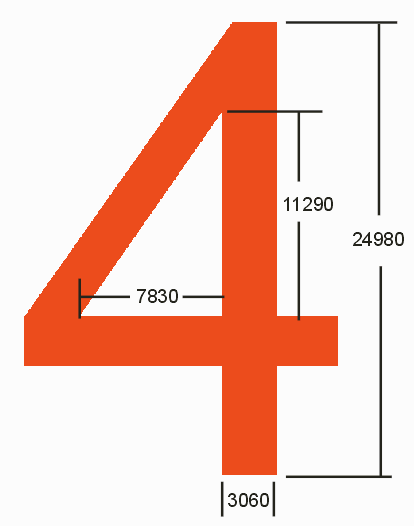
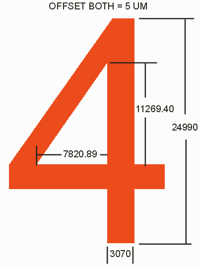
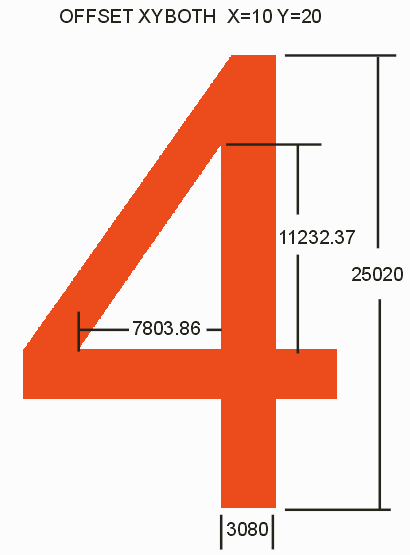
OffsetOffset, also known as edge bias, compensates for etch factor. There are two different modes. Below you can see one of the geometries without any sizing applied. Dimensions without any offset applied. Both - if both is selected then the X and Y directions are sized equally. The illustration below shows the dimensions when a value = 5 um has been applied to both X and Y. Offset of 5 um in both X and Y XYBoth - Allows independent offset (edge bias) values for X and Y. In the example below the X offset = 10 um and the Y offset = 20 um. |