What's all this about RS274X Anyway?

Steve DiBartolomeo
Applications Manager
Artwork Conversion Software, Inc.
© 1995 Artwork Conversion Software, Inc.

Introduction

If you're a PCB designer you're probably hearing more and more about extended Gerber - RS274X. The latest versions of many PCB layout programs either offer RS274X as an option or only output RS274X-- such as Cadence's Allegro.

Benefits of RS274X

RS274X includes many high level commands and controls that let the creator of the Gerber data specify the photoplot very precisely - much more so than RS274D which entailed passing a lot of critical information separately from the data file.

What is RS274X anyway?

It is an extension to standard RS274D (commonly known as Gerber) that includes:

  • embedded format, unit and data information
  • embedded apertures
  • custom aperture definitions
  • film control statements
  • multiple layers embedded in a single file
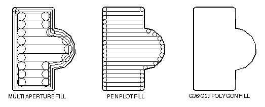
  • special polygon fill commands

This document assumes that you are familiar with the basic Gerber commands - if not you may wish to first review the article Apertures, D-Codes and Plot Files which summarizes basic Gerber.

Some of the embedded information we mention here is actually available, although rarely used, in the RS274D specification.


Where to Get the Official RS274X Spec?

The RS274X specification was developed by Gerber Scientific. Gerber was purchased by Barco, then Barco by Mania, a Belgian company. The spec now resides with UCAMCO (formerly Barco ETS). The most recent Gerber specification is now available as a downloadable PDF: Gerber File Specification 2015.10 2.66 MB


Embedding Format Info in the 274X Header

RS274X includes a statement that embeds key information about the format, zero suppression and data mode into a single line:

  • format (x,y)

  • zero suppression (leading, trailing or none)

  • coordinates (absolute or incremental)

format statement components
where:

L  = leading zeros omitted
T  = trailing zeros omitted


A  = absolute coordinate mode
I  = incremental coordinate mode

Xa = format of input data
Yb = format of input data


Examples

 %FSLAX24Y24*%
Format Statement Leading Zeros Suppression, Absolute Coordinates format=2.4

 %FSTIX44Y44*%
Format Statement Trailing Zero Supression, Incremental Coordinates, format=4.4


Embedded Units

RS274X files can use coordinate and aperture units of either inches or millimeters. The statements:
%MOIN*%     indicates inches
%MOMM*%     indicates millimeters

Controlling Image Polarity

When using RS274D one had to set the photoplotter manually on the desired polarity of the film. If the operator didn't pay attention or got confused then your film came out wrong. With RS274X, a command near the beginning of the file can invert the film's polarity.

274_f2.gif

%IPPOS*% - positive (left)

%IPNEG*% - negative (right)

Do not confuse image polarity with individual layer polarity. It is possible to build up a very complex plot by combining individual dark and clear plots and then setting the overall polarity of the film.


Embedded Aperture Definitions

One of the major shortcomings of the old RS274D spec was that the definition of each aperture was not part of data file; instead it was transferred manually on paper or as a text file similar to what is seen below:

     Aperture Definitions
     D-code     Shape       SizeX       Size Y
     d10        round       0.010
     d11        square      0.030
     d12        rect        0.060       0.020
     d13        thermal     0.050
     d14        oblong      0.060       0.025

Some apertures are obvious - the round, square and rectangle. But both the oblong and the thermal are subject to the photoplotter's operator's interpretation as shown below.


274_f3.gif

Basic Thermal     Rotated Thermal     Square Thermal


With 274D, the exact shape of the thermal shape was a job for the photoplot operator; there was significant amount of effort and expense involved in creating these custom apertures and libraries had to be maintained. With 274X even complex apertures are described using macros that the photoplotter synthesizes on-the-fly.


The Basic Aperture Definitions

RS274x includes several "standard" apertures since these represent more than 90 percent of the flash types used:

  • circle
  • rectangle
  • obround
  • polygon

These are all assumed to be centered and can be defined with a round or rectangular hole if desired.


Standard Circle

%ADD{code}C,{$1}X{$2}X{$3}*%

where

AD -      aperture description parameter
D{code}   d-code to which this aperture is assigned (10-999)
C         tells 274X this is a circle macro

$1        value (inches or mm) of the outside diameter
$2        optional, if present defines the diameter of the hole
$3        optional, if present the $2 and $3 represent the size of
          a rectangular hole.

Circle Examples

274_f4.gif
%ADD21C,.100*%                      (a) 0.10 diameter circle on d21

%ADD22C,.100X.050*%                 (b) 0.10 dia circle with 0.05 hole on d22.
                                      
%ADD23C,.100X.050X.050*%            (c) 0.10 dia circle with 0.05 square hole on d23.
                                      
%ADD24C,.100X.050X.025*%            (d) 0.10 dia circle with 0.05 x 0.025 rectangular hole on d24.


Standard Rectangles

%ADD{code}R,{$1}X{$2}X{$3}X{$4}*%

where

AD -      aperture description parameter
D{code}   d-code to which this aperture is assigned (10-999)
R         tells 274X this is a rectangle macro

$1        value (inches or mm) of rect's length in X
$2        value if rect's height in Y
$3        optional, if present defines the diameter of the hole
$4        optional, if present the $2 and $3 represent the size of
          a rectangular hole.

For details on the obround and polygon (which are rarely used) see Gerber Format Guide, Doc 0000-000-RM-00.

Aperture Macros

The more general aperture macro can be thought of as a type of programming language where one builds up a complex aperture definition from a series of simpler primitives. Macros are almost required for properly defining thermal reliefs - and since thermal reliefs are very important in power and ground planes we'll do a detailed example of macros using the thermal primitive.

Macro Primitives

Remember we said a macro is like a programming language - the complex aperture is built from one or more shapes called primitives. Available primitives include:


Primitive Name      Primitive Number      Description and Parameter Number

Circle                  (1)               round

Line Vector             (2 or 20)         rectangle defined by endpoints
                                          width and rotation. Square ends.

Line Center             (21)              rect - defined by center and length, width
                                          and rotation. Square ends.

Line-Lower Left         (22)              rect - defined by lower left coordinate,
                                          length, width and rotation.

Outline                 (4)               outlines an area defined by coordinate pairs.
                                          max vertice=50.

Polygon                 (5)               a regular polygon with 3-10 sides. defined
                                          by center, outer diameter and rotation.

Moire                   (6)               target defined by center, number of circles
                                          circle thickness, cross hair length, thickness
                                          and rotation.

Thermal                 (7)               thermal relief defined by outer diameter, inner
                                          diameter, crosshair thickness and rotation.

Aperture Macro Example - Thermal Relief

The thermal relief is so important that it has its own primitive - even though it could be built from other primitives.

274_f5.gif

      %AMTHERM100*7,0,0,0.100,0.050,0.025,0.0*%
      
      %ADD32THERM100*%                           assigns THERM100 to d-code 32
      
      where

      AM         -       aperture macro
      THERM100   -       name of the macro
      *          -       terminates name
      7          -       primitive 7, which is a thermal relief
      0,0        -       first two parms: x,y center
      0.100      -       third parm: outer diameter (solid black see (a) above)
      0.050      -       fourth parm: inner diameter (clear see (b) above)
      0.025      -       fifth parm: crosshair width (clear see (c) above)
      0.0        -       sixth parm: crosshair rotation (not used here)


Multiple Internal Layers

When photoplotting was done by vector machines which directly exposed a piece of film through a shutter and aperture, the concept of multiple internal layers had little use, since once film was exposed the process could not be reversed. However the development of raster based photoplotters which used computer memory to compose a bitmap image prior to exposing the film enabled a user to combine multiple layers and to easily remove data using one layer that had be laid down by a previous layer.

With RS274, the photoplotter operator had to key in the various input layers (individual RS274 files) and set the "polarity" of the layer manually - see a typical instruction list provided to an operator below:

Plotting Instructions for Board XYZ

Film1: top
targets.gbr                 pos
comp.gbr                    pos
padmaster.gbr               pos

Film2: bottom
targets.gbr                 pos
sold.gbr                    pos
padmaster.gbr               pos

Film3: vcc
vcc1.gbr                    neg
clearance.gbr               neg
traces.gbr                  pos

RS274X includes two special commands, %LPD*% (Layer Polarity Dark) and %LPC*% (Layer Polarity Clear) that apply to internal layers within an RS274X file. With a few judicious LPD/LPC commands combined with the IP (image polarity) command one can build up complex ground planes quickly and easily. In the example below we will show how the LPD/LPC can be used to put a circuit trace easily on a power plane.

The main difficulty with putting a circuit trace on a power plane is clearing away the metal around the circuit trace and it's associated pads. With standard Gerber the layout software often had to fill in with small strokes the entire powerplane metal area except where the clearance would be. This results in a very large and unwieldy Gerber file.

When creating such a Gerber file in 274X we can use the LPC (clear layer) to draw the trace.

G04 Image Parameters ***
%MOIN*%
%FSLAX24Y24*%
%IPNEG*%            this will reverse polarity of the entire film, eliminating the need to 
                    stroke fill the metal area of the powerplane.

%ADD10C...*%        here we define some round apertures and a thermal  
%ADD11C...*%
%ADD12C...*%
%AMTHERMAL*...*%
%ADD13THERMAL*%
G04*
%LNINTERNAL_VCC*%   this is our basic vcc powerplane layer consisting of clearance pads, thermal reliefs,
                    the outer trace that defines the board edge, and the clearance for the inner trace.

%LPD*%              indicates digitized data is dark. However when the entire film is reversed the 
                    digitized data will be clear.
G54D10*
data
data
data

G04 NEW LAYER ***
%LNTRACE_VCC*%      this is a new internal layer which will be used to define the circuit trace and two pads

%LPC*%              note that the data here is clear or reversed out. When the entire film is negated 
                    the digitized data will be black on the film.
G54D12*
data
data
data
M02*                end of the job
          

The series of images below show how a ground plane can be easily drawn, a trace within the ground plane is placed and substracted, and the entire image is then reversed.

274_f6.gif

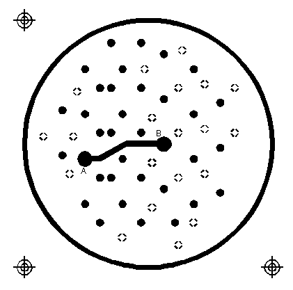
Figure 1: This is what the data on the layer Internal_VCC would look like if a) it were not reversed out and b) we did not yet deal with the next layer. Note the large pads at A,B and the fat clearance trace.


274_f7.gif

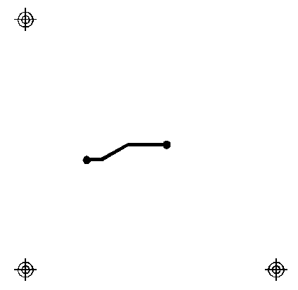
Figure 2: Here is what the data for the layer TRACE_VCC would look like a) before the image is reversed b) before the LPC directive is implemented. Because of LPC, this data will be "subtracted" from the data laid down by the first layer.


274_f8.gif

Figure 3: The LPD layer, Internal_VCC merged with the LPC layer TRACE_VCC layer but before polarity reversal.


274_f9.gif

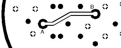
Figure 4: The final image on the film after the IPNEG directive has reversed the polarity of the merged internal layers.


G36/G37 Polygons

The G36/G37 polygon command precedes the RS274X spec but only the raster based photoplotters supported it. It is a very powerful command and will see more use in the future for describing complex data often encountered in IC packages, RF and microwave circuits and analog devices.

When the photoplotter sees a G36* command it immediately changes mode - it now ignores any aperture setting and treats each draw command as the edge of a polygon to be filled in. The application creating the Gerber file should create simple clean polygons.

274_f10.gif

Sample Usage of G36/G37


         G04 G36/G37 Polygon Example ***
         %MOIN*%             set the units to inches
         %FSLAX24Y24*%       set the format statement
         %IPPOS*%            set polarity to positive
         
         %ADD10C,,,*%        here we define some apertures
         %ADD11C...*%
         %ADD12C...*%
         G04*
         %LPD*%
         G54D10*            select D10 [not mandatory to select a D-Code]
         G01*               set linear draw mode
         G36*               switch into polygon mode. The shape of D10 no longer matters.
         X123Y123D02*       move to initial position with pen up
         X234D01*           draw a line (edge)
         Y456D01*           draw a line (edge)
         X234D01*           draw a line (edge)
         Y123D01*           draw a line (edge) back to original start
         G37*               end polygon mode.

It is possible (and fairly common) to switch back and forth between G36/G37 and standard draws and flashes. Many PCB tools use round draws for circuit traces, flashes for pads and G36/G37 for any shapes such as power planes.

Tools for RS274X

For information about Artwork's products that view, plot, and manipulate Gerber data please visit our GERBER Page.