Recently one of our customers wanted to use gbr_rip to extract thousands of small windows from a single layer of a very dense and large PCB panel. These small windows were generated by an inspection machine that looked for defects. The idea was to compare the images of the defects generated by a camera against the bitmap of the design data.

The rate at which gbr_rip was extracting these small bitmaps windows was insufficient to support the desired throughput for inspection equipment and the subsequent analysis of the defects.
The Problem?
GBR_RIP was originally designed to rasterize the entire panel using only a relatively few number of very large windows. So it was not optimized to handle a large number of very small windows and was reloading the geometry data from disk for each window call.
The Solution
The solution was to rewrite the rasterizer so that it cached the input data in a way that allowed the program to re-use it for each window call.
Multi-Window Usage
To use the multi-window option the user must first have the multi-window license in place. Then use the -wplot argument followed by the @filename directive to point to a file containing the list of window corners (i.e. LLx,LLy,URx,URy)
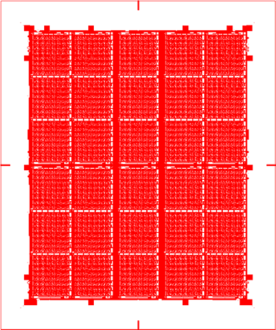
In order to show the efficiency and speed of the multi-window option, we ran a test using a large and dense Gerber file (layer1.gbr) of a panelized BGA.

RS-274X panelized board. Panel is ~16 x 20 inches in extents.
To generate a large number of windows, a random window generator program was written to produce 1000 windows; this data was saved to a file called rand.txt. Each window is 0.0189 wide by 0.0142 inches high and the DPI we will use is 54,000. We want to generate 1000 TIFF bitmaps (packbits compression) and write them to disk. Each bitmap is 1024 x 768 which matches the size of the camera sensor.
You can see a snippet of the rand.txt file below. Each line consists of the 4 corners of a window: LLx,LLy,URx,URy.
3.243350,14.717415,3.262250,14.731615
2.124791,16.974720,2.143691,16.988920
9.349831,15.389520,9.368731,15.403720
11.075833,7.581411,11.094733,7.595611
13.805661,14.627416,13.824561,14.641616
7.377948,7.299853,7.396848,7.314053
11.681642,5.549137,11.700542,5.563337
6.600475,15.220838,6.619375,15.235038
13.371963,11.457482,13.390863,11.471682
11.426536,2.231088,11.445436,2.245288
7.524861,2.735534,7.543761,2.749734
8.867961,7.991825,8.886861,8.006025
9.218859,18.633601,9.237759,18.647801
13.712744,3.732397,13.731644,3.746597
The Command Line
Here is the command line used:
C:\WCAD\GBRRIP64\gbr2tiff64.exe     full path to the command line app

"%CD%\layer1.gbr"                   the input ODB++ file

-274X                               a directory for holding temp files

"-wplot @%CD%\rand.txt"             window plot using file input

"-pack:%CD%\output\win.tif"         output tiff packbits using this base name

-ram:128                            the amount of RAM (in MB) to allocate
                                    for the bitmap buffer.

-dpi:54000                          The DPI

-status                             display status/progress

-units:inch                         command line arguments (and windows) in inches
The Results
CPU - Intel Core2 Quad CPU Q8400 @ 2.66 GHz
RAM - 8 GB
Disk - mechanical 7200 RPM
Number of TIFF Output Files: 1000

Time to produce 1000 bitmaps: 06:08 min:sec
This works out to 0.37 seconds per frame.
The throughput is now sufficient to properly support the hardware used for the high speed inspection and analysis of complex PCBs.