Running the 144 Pin Leadframe with ANF Output

This example uses a simple 144 pin leadframe with output to Ansoft's ANF format. Items of Note are:

    Leadframe Drawn as Reversal - because of the way leadframes are manufactured, the CAD layout is often drawn in reverse -- i.e. the non digitized area represents metal. This poses two problems: first, the Gerber file must be reversed; fortunately NETEX-G has such a reversal option. Second, a clipping window must be defined around the perimeter of the data -- if no such window is defined then all of the nets will be tied together. NETEX-G has a Window specification that allows one to clip just inside the perimeter of the leadframe.

    Padstack for Solder Balls - In order to use the ANF results in a program such as HFSS or Spicelink 3D one needs in the ANF file a padstack to which solder balls can be attached. The solder balls act as one "end" of the net to be analyzed. Since leadframe data doesn't come with ball pads, we created a simple Gerber file with square pads where the end of the leadframe is to be simulated. This was dropped into NETEX-G as a drill file which produces the required via/padstack.

    No dielectric needed between wire layers or wire/metal layers - the Ansoft tools recognize wires as a special entity and when building up the stackup it is not necessary to insert a dielectric between wire layers nor a dielectric between a wire layer and the metal layer below it.

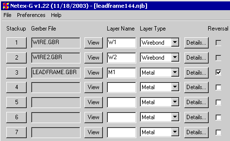
This is a single layer leadframe. There is a single Gerber file for the leadframe and two Gerber files for the wires. The NETEX-G crossection is shown below:

leadframe crossection

The stackup shown above is set for Ansoft's Neutral File (ANF output)
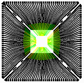
144 pin leadframe


Layer Stackup
ANF

Select the correct Gerber file for each layer starting at the top of the stackup and working down. Since our target output is ANF we do not need a dielectric between the wire layers and the top metal layer.

Notice that the reversal box for the metal layer is checked. This tells NETEX-G to reverse the polarity so that the digitized data is not metal.

layer stackup


Preference Setttings

preferences

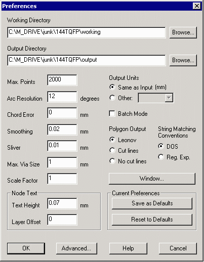
Before running NETEX-G check your preference settings.

Working Directory -- all temporary files generated by NETEX-G will be written to this directory. It is useful to isolate them in one place away from the input/output files so that they can be easily deleted once the job is complete.

Max Points -- max number of vertices per output polygon. If exceeded, the program breaks the polygon into two (or more) less complex ones. In this example it has been set to 2000 vertices.

Window -- for this example it is absolutely critical to define a window. By setting the window slightly smaller than the size of the data, the individual leadframe fingers are "cut" out -- otherwise they would be all shorted together.

Chord Error -- parameter to convert arcs into segments. This value is the max difference between the ideal arc and the approximation chord. Chord error uses more segments for large arc radii and less for smaller arcs.


Smoothing -- smoothing is a routine that reduces the vertex count after booleanization by removing closely space vertices. The parameter shown here, 0.02 mm will remove a vertex if a neighbor is within 0.02 mm of it.


Sliver -- removes tiny slivers of isolated metal that are generated due to arc approximations and the boolean process.

Max Via Size -- prevents NETEX-G from assuming that large round pads are vias. Set this value slightly larger than the diameter of the maximum via you expect to use in the conversion.


Scale -- scales output data as needed. Default=1.

Polygon Output -- for ANF output select Leonov polygons.


Output Units -- by default the output units match the Gerber units (mm or inch) For some output formats such as GDSII units such as microns are preferred. The output units can be modified using this option.


Drill Data to Vias

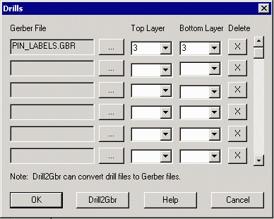
The single layer leadframe has no vias (the pseudo vias from wire to leadframe are automatically generated) but we still use the drill to create an array of padstacks on the metal layer. These padstacks will be used by Ansoft to attach solderballs; the solderballs act as one end of the net.


The gerber file, PIN_LABELS.GBR, was created manually in order to provide padstacks for the Ansoft products. It is placed on stackup 3 (the leadframe) but does not go through any layers.

drill dialog

Select an output file name and save the job file (the job file contains all of your settings and can be reloaded later to run this job again ...). Now execute NETEX-G. Extracting all the nets and converting to ANF should take less than a minute.

Results

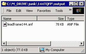
When the extraction is complete an ANF file should reside in the output directory. If you would like to view the ANF file yourself, you can download it from here:

leadframe144.anf.zip 182 KB.
ANF output file


ANF Output

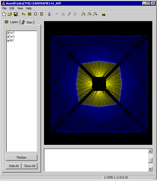
The output produced by NETEX-G for this example is an Ansoft Neutral File. stream file. The screen shot below uses Ansoft's ALINKS program to display the layout. The user would select the desired nets in ALINKS, set the wirebond parameters and attach the solder balls. After doing this the results are exported to formats supported by SpiceLink, HFSS or Turbo Package Analyzer.

ANF File displayed in ALINKS 2.5


Back to Benchmark Page