
The ODB++2GDS translator can be run from a GUI or from the command line.The GUI interface is described here.
GUI
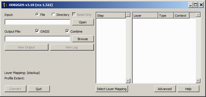
To start the GUI double click on the link to the file: odb2gds64.exe (on Windows). The main dialog will open:
Loading an Input File
To load an input ODB++ file, first select the correct radio button: "File" indicates the ODB++ is available as a .tgz (tar gzipped) file. "Directory" indicates that the ODB++ data is available as a directory hierarchy.
Use the Browse button to open a file dialog and select either the appropriate .tgz file, or if opening a directory hierarchy, navigate until you get to the top of the ODB++ folder hierachy.
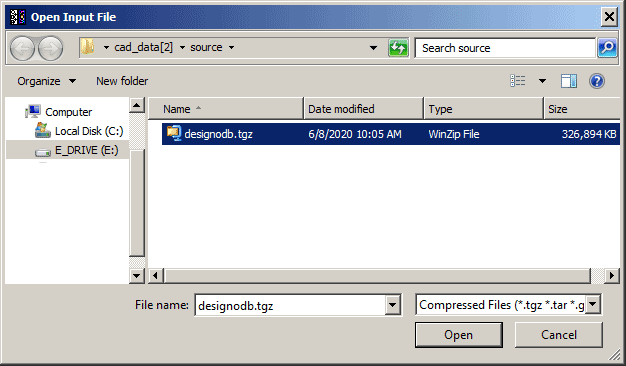
Select the desired file and hit OK.
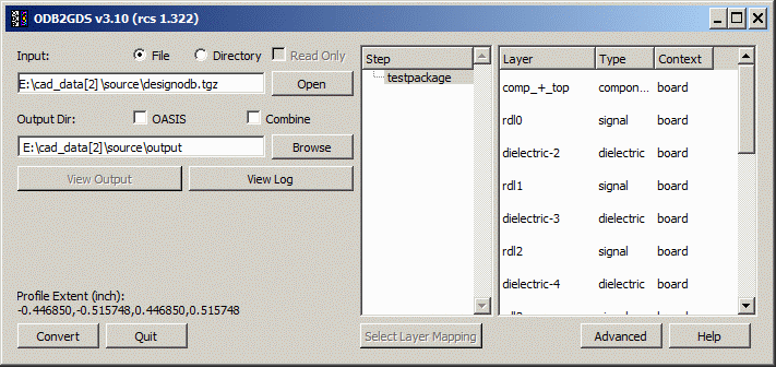
The ODB++ file will be uncompressed (if a .tgz file) and scanned. Depending on the size of the file this may take only a couple of seconds or as long as a minute. The main dialog will now be populated with information:
Step
An ODB++ file must have at least one step, but may have many steps. It is possible in ODB++ to have many different circuits (each in its own step) and then have a step that "places" or arrays these circuits along with adding other essential board layout.
In the example above, the step labeled pcbdata represents a single circuit. The user is responsible for deciding which "step" to process if there is more than one step defined. Only one of the available steps can be selected.
Layer
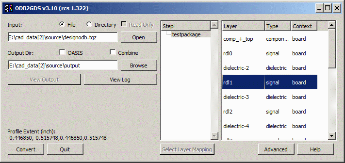
The ODB++ to GDSII converter will display a list of layers that are defined in the ODB++ input. Not all layers listed necessarily contain data. The user needs to know the name(s) of the layer to convert. The user can select multiple layers to convert.
Combine Layers
If the Combine option is checked, the translator will create a single GDSII files; each ODB++ layer selected will be mapped to a unique layer in the GDSII (or OASIS) file. If not checked, then each ODB++ layer selected will produce a separate GDSII (or OASIS) file.
Select Layer Mapping
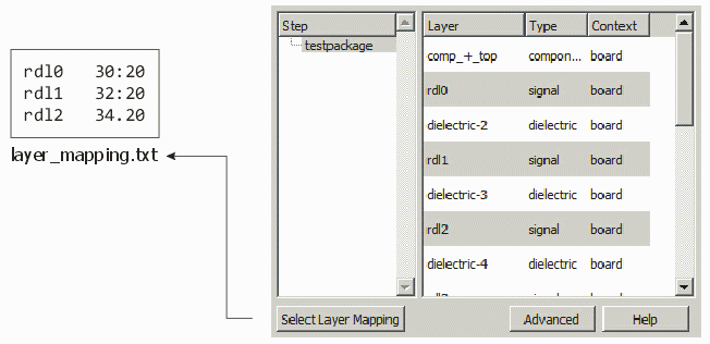
If you wish to control the mapping between the ODB++ layer name and the GDSII (or OASIS) layer number and datatype then you need to press the Select Layer Mapping ... button. You will first have to prepare a text file with the mapping. The file uses the following syntax:
odb_layer_name    layer:datatype
odb_layer_name    layer:datatype
odb_layer_name    layer:datatype
For example if we want to convert ODB++ layers rdl1, rdl2 and rdl3 into GDSII layers 30:20, 32:20 and 34:20 then our mapping file would look like this:
rdl1    30:20
rdl2    32:20
rdl3    34:20
If you don't care about the datatype then you can simply write:
rdl1    30
rdl2    32
rdl3    34
and the datatype will default to zero (0).
Once you have created the mapping file you can press the Use Layer Mapping ... button and select it using the file browser.
OASIS
The default output will be GDSII unless the OASIS checkbox is checked. (Note - a separate license for OASIS output is needed. If not present, the OASIS check box will be grayed out.
Output Dir:
To control the output file name and location, click on the Browse button. Then using the file dialog select the location and name. By default, the location of the output file is determined by the working directory and the output file name is based on the input file name.
The Advanced Settings dialog has three tabs which contain settings one may need for special use or settings which don't change from conversion to conversion. To review the options, click here.