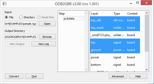
The ODB++2GBR main window enables the user to select the file (or directory hierarchy) for the ODB++ data, open (i.e. scan) the database, select a step and one or more layers to convert. The Advanced button controls program configuration and behavior.

The ODB++2GBR main window.
Input:
File - if you want to open a .tgz file select the File radio button.
Directory - if the ODB++ has already been unzipped and untar'd into a directory select this button.
Open - use the Open button to select either the input file or top level directory.
Output Directory - specify where the Gerber files should be written..
Step
Step - select one of the available steps to convert..
Layer
Layer - select the layers to convert. Use Ctrl and Shift to select multiple layers.
Buttons
View Output - After conversion, click on View Output to start up GBRVU and view the Gerber files that were just produced.
View Log - After conversion, click on View Log to show the log file in a text window.
Convert - Starts the conversion. Only click after opening an ODB++ file/directory, Selecting a Step and selecting Layers.
Advanced - Opens the Advanced Settings window
Quit - Quit the program.
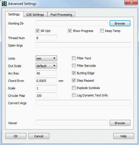
There are three tabs available for Advanced Configuration. The most commonly used configuration parameters are grouped into the first tab labeled Settings.

Working Directory - specify the working directory where temporary files are written.
Thread Number - if you have more than one core, can specify additional raster threads. Do not exceed one thread per core.
SR Opt - Optimizes step repeat, where the software combines SR child steps together when possible. This is the default behavior. There is an option to turn it off because sometimes child steps overlap each other and combining it might produce an error with scratch data.
Keep Temp - If checked, temporary files are not deleted upon closing the program.
Show Progress - If checked, a progress bar is displayed during conversion.
Open Args - special arguments passed to front end that handles file opening.
Units - Specify units for your Gerber data - MM or Inches.
Out Scale - There are several options available:
default - ignore all out_scale
sf - enforce global scaling by way of %SF
scale - enforce global scaling by way of explicit scaling
local - perform scaling with .out_scale control
ODB++ makes extensive use of arcs in the data. This parameter allows the user to specify the angle subtended by the chords used to approximate the arc.
Chord ErrorODB++ makes extensive use of arcs in the data. This parameter allows the user to specify the error between the arc and the approximation. The number of segments in each arc is adjusted to meet this error value. Set this value after setting units.
Scale - scales data as specified.
Circular Map - Controls the surfaces that will be converted to round flash. The default is 100 where if there are at least 100 round surfaces of the same diameter, they will be converted to a round flash. If it is set to zero, the round surfaces will not be converted into round flashes.
Filter Text - Filters out text from Gerber output.
Filter Barcode - Filters out barcode from Gerber output.
Butting Edge - If checked, output polygons are generated with butting edges instead of internal cutouts.
Step & Repeat - If checked, repeated geometries are implemented the step-and-repeat (SR) command in Gerber.
Explode Symbols - if checked, ODB symbols will be exploded in the Gerber and not output as macros.
Log Dynamic Text Info - If checked, dynamic text generated is reported in the log file
Convert Args - Special arguments to control the output (debugging)
Viewer - Specify the path/program name to launch in order to view the Gerber files. If it's not specified, you will be prompted to select a viewer when you try to view the output.
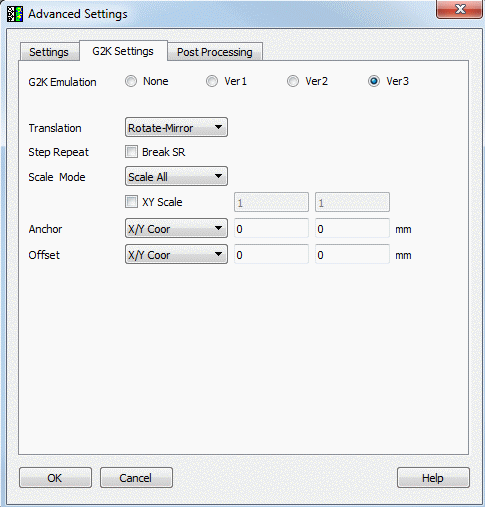
ODB supports g2k arguments which define emulation mode for certain plotter manufacturers. This controls in this menu allows the user to select which kind of emulation to use when converting ODB++ files to Gerber. This mostly effects scaling and mirroring.

G2K Emulation
Most users should select None. The other 3 emulations were created for a specific client who required control of a specific range of photoplotters.
Ver1
allows the user to perform Scale, Rotation, and Mirror based on Anchor Datum set to the Profile Center.
does not allow the use of SF, IR, MI, IP, IO commands in the output Gerber file.
assumes that mirror occurs before rotation.
Ver2
similar to Ver1 but does not break STEP and REPEAT.
Ver3 - has additional transformation options enabled.
Translation - No Mirror - Don't perform mirror during the conversion.
Translation - Rotate Mirror - Perform rotation first and then mirror.
Translation - Mirror Rotate - Perform mirror first and then rotation.
XY Scale - User can define a different scale along X and Y.
Anchor - User defined anchor point for the scaling.
Offset - User defined offset along X and Y.
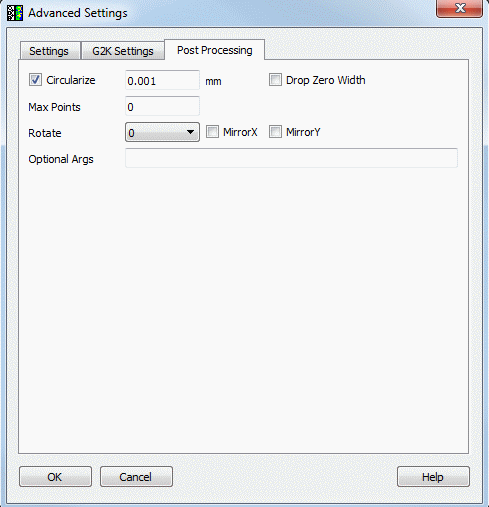
In this menu user controls post processing settings.

Circularize - directs the processor to convert a series of line segments into an arc using a user defined tolerance.
Drop Zero Width - directs the processor to delete 0 width draws.
Max Points - directs the processor to create polygons with user defined max points per polygon.
Rotate - Rotate the output file.
MirrorX - Mirror output file along X axis.
MirrorY - Mirror output file along Y axis.
Optional Arguments - Special arguments to control the output (debugging).