web page header logo


Introduction

The ODB++ Database is a complex complete description of a printed circuit board that is often requested by board manufacturers in order to consolidate all of the information needed to produce and test the board in one job. The Gerber database is designed only for the purpose of producing the artwork's necessary to etch each layer of the final printed circuit board.


A ODB++ job is one directory composed of many subdirectories and files. Of the various subdirectories, we need only consider the following that contribute to layout data:

The Matrix

The Symbol

The Step

The Layer


Matrix

The Matrix folder and file lies at the top of the ODB++ hierarchy; it takes the form of an array in which the rows are the job layers and the columns are the job steps. The matrix contains for each row additional information such as the name, type, polarity and context. The matrix is also crucial in defining the physical order of the layers and the relation of drill layers (through, blind, buried, etc.) The converter ignores stackup information and is only interested in layer types and polarities.

There must be one matrix folder and associated file.


Symbols

Symbols are primarily used to draw pads on the PCB. Hence they correspond to RS274X flashes. In ODB++ symbols can be built from primitive drawing elements: lines, arcs, polygons, surfaces and pads. There are also a large number of "standard" symbols which are controlled via their parameters. The converter supports both types of symbols.

If only "standard" symbols are referenced in the feature files then the symbol directory and associated feature file need not be present.


Steps

ODB++ Steps are "containers" which essentially describe a multi-layer object - a PCB, a panel outline, a test coupon or similar item. Within the step are various files. Most of these are not of interest in generating artwork except for the layer/feature files.

There must be a minimum of one step folder. However there may be many step folders and a step may reference other steps for the purpose of arraying.

Layers

ODB++ Steps contain a series of layer folders - each layer folder contains a feature file which lists the actual draws, flashes and surfaces that create the board artwork.


Sample ODB++ JOB Hierarchy

In the tree shown below the ODB++ job has two steps - a PCB which contains a single design of a PCB and a step called panel, which has no features of its own but which references the pcb step in order to produce four images for the panel.
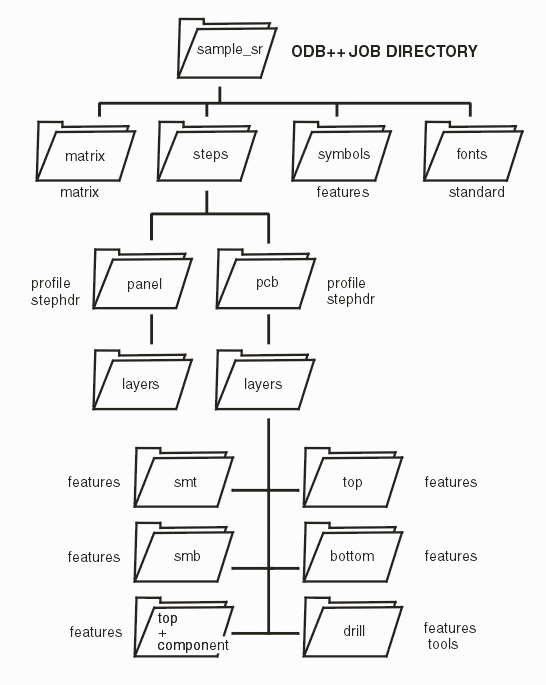

ODB++ hierarchy (only folders and files that apply to RS274X output are shown.)


Download

Revision History

Price