About the Wafer Map
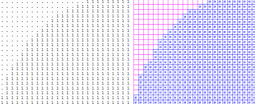
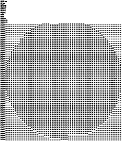
The wafer map is normally an ASCII file -- though we have seen some binary ones coming out of probers -- that may include a short header and then is followed by a number of rows that identify a die by some sort of symbol.
If you replace each of these symbols with a rectangle of the correct size, you get essentially the pattern of the die on the wafer.

Now this is already very useful but the problem is that just from the wafer map data, one does not know exactly how this array of die is placed on the wafer. When stepping the wafer there is normally a small but important offset. But wafer maps do not contain the offset coordinates.
So where do we get the offset amount?
Shot Map
A shot map is a essentially a description of the placements of the reticle used to expose the wafer. Normally a small number of die are written to a reticle plate (at 4x or 5x) and then this reticle is placed into a stepper which makes a number of exposures -- also known as "shots" -- across the surface of the wafer.
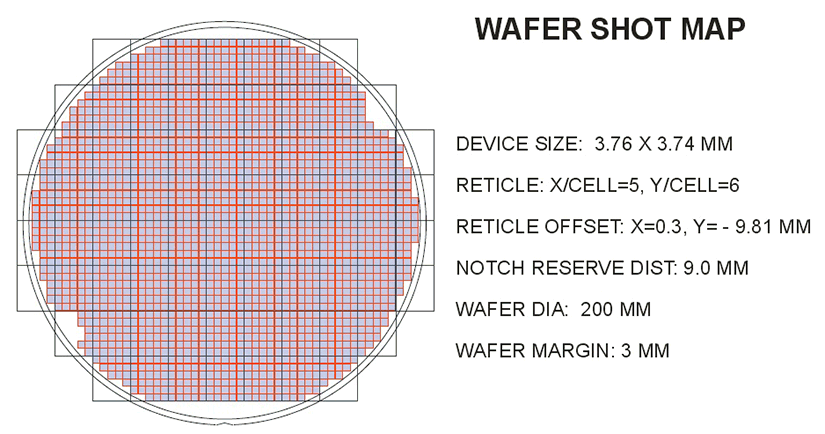
Unfortunately there is no standard data format for a shot map - in most case the packaging engineer gets a "snapshot" of the stepper controller's screen similar to the one shown below:

The shot map does tell you exactly where the die are positioned because in addition to the stepping information it includes the offset information for the central "shot." But it does not contain any information about what die have been "knocked" out or if there are any missing die where alignment marks have been placed. Only the wafer map contains that kind of information.
Merging the Wafer Map and the Shot Map
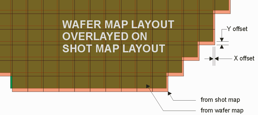
It is clear that if we take a layout generated by the wafer map and a second layout generated from the parameters of the shot map we should be able to overlay one over the other. Once overlaid, it is simple to measure the offset between the two layouts. We can then use that offset when converting the wafer map layout into a template for our redistribution mask set.

NEXT - Program Interface and Functions
|


