web page header logo


Steve DiBartolomeo
Steve DiBartolomeo
Applications Manager
Artwork Conversion Software, Inc.

Introduction
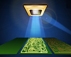
apps-digital-light-exposure.jpg

The combination of lower cost lasers, high performance DLPs and fast computers has made direct imaging lithography much more practical today than it was a few years ago. It is now possible to build machines that can directly expose lines in the photo resist of a few microns over substrates areas covering 500 mm x 600 mm. In order to obtain the desired throughput, multiple photo heads can be mounted on a single machine.

Artwork specializes in high resolution rasterizers for Gerber, ODB++ and GDSII that are designed to produce the raster bitmap needed to drive these direct exposure machines.

However because of the nature of the DMD optical chain, a standard bitmap is only an intermediate step in preparing the data needed to drive the exposure system. The bitmap must be sliced into a number of "bands" that match the width of the DMD.
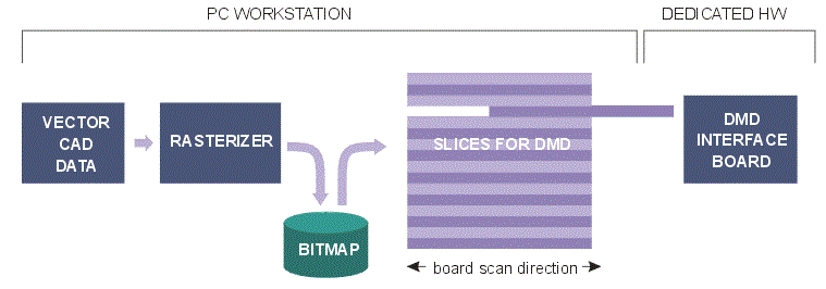

data preparation flow for dmd lithograpy

How many pixels are we talking about?

Let's consider a 500 x 610 mm image area with a pixel grid size of 1 um. The number of pixels after rasterization is:

500 mm x 610 mm x 1000 pixels/mm x 1000 pixels/mm = 30.5E10 pixels

That's approximately 38.1 GBytes worth of pixels1.


Note 1 - it is not even possible to store this on disk as an uncompressed TIF file as the TIF file format does not support files larger than 4 GBytes. Instead we compress it using packbits which often gives us 10X to 20X compression. However this adds computation costs both in writing the bitmap to disk and later when slicing it.


Scanning the Image Area

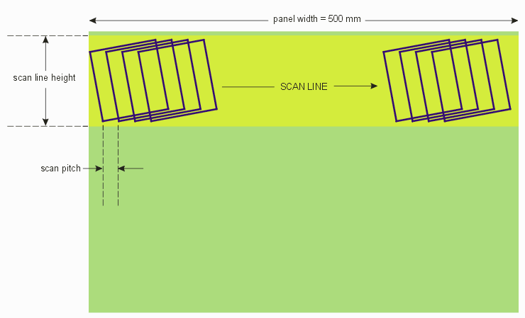
The beam modulated by the DLP is scanned over the panel - more likely the panel is actually "scrolled" under the optics along one axis. This should expose a narrow swath of the panel per DLP. The panel is then shifted one swath width (normally a bit less to allow for some overlap between swaths) and then scrolled again. The illustration below shows how this works for a system that uses 7 DLP modulators. (from Maskless Technology's description of their machine.)

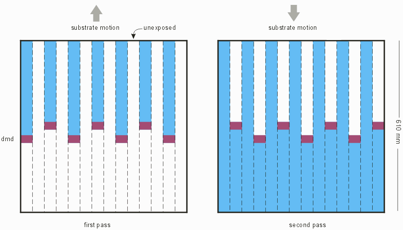
dmd scan over substrate with two strips

The direct exposure writer uses multiple heads. The substrate is scrolled in one direction - then shifted over and scrolled back in the other direction.


Rotation of DMD along Scan Direction Complicates Data Processing

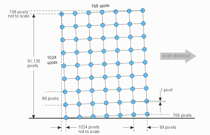
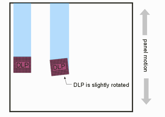
The DMD is rotated very slightly from the scan direction. This is done to control the spacing between pixels in the direction of the scan. Such a rotation require that the bits used to control the DMD be extracted by a computation. The computation is not particularly difficult -- what is difficult is the sheer number of pixels that have to be recomputed and delivered as DMD "frames."


dmd is rotated slightly from direction of scan in order to achieve desired pixel overlap.

Why Rotated?

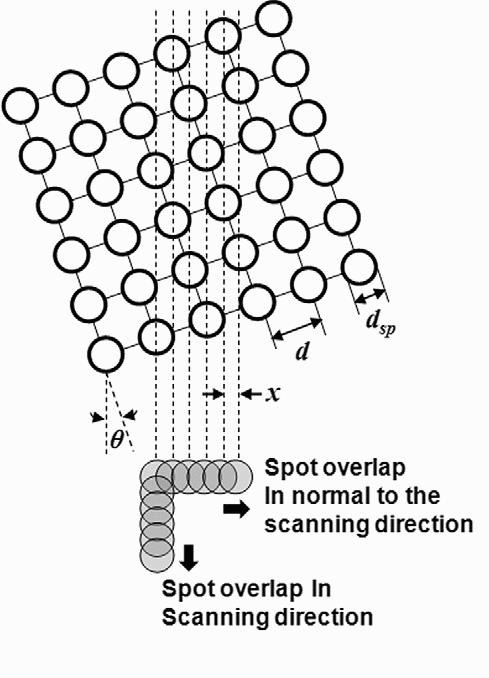
When we rotate the DMD at a small angle, we can control the spot overlap perpendicular to the direction of motion. Our DMD spot diameter and spot spacing is much much larger than the pixel resolution we wish to put down onto the substrate. [Ed note: TI reports that for a HD DLP the center-to-center spacing is 10.8 um.]


spot overlap computation diagram

The amounts of spot overlap in the scanning direction and its normal direction are determined by the stage speed and the rotation angle of the DMD, respectively.

The spot overlap in the scanning direction can be simply written as

equation1.gif

where Osp,scan is the spot overlap in the scanning direction, Fr is the frame rate of the DMD, dsp is the spot diameter, and Vs is the stage speed. The rotation angle of the DMD also satisfies the equation,

equation2.gif

where x denotes the horizontal spot separation, d is the pitch size of the point array, and h is the rotation angle of the DMD.


The spot overlap in the normal direction of the scan can be easily estimated as:

equation3.gif


Converting from Raw Bitmap to DMD Scan Frames

Rotating the DMD slightly requires a massive amount of bitmap computations in order to supply it with the correct input. Let's assume that we have already computed our complete bitmap for the panel which we previously saw required 38GB of uncompressed space (we are certainly storing it on disk in compressed format)

As the DMD is "scanned" across the panel (or the panel is scrolled across a fixed DMD) it needs to be provided with a large number of 1024 x 768 bitmaps.

how much memory needed to build a scan line?

How much of the source bitmap do we need to load into our processor's memory in order to generate these frames?

To do this computation let's make the following reasonable assumptions:

frame = 1024 x 768
projected spot pitch = 89
pixel grid = 1
diagram of rotated frame and pixel computation

The "height" of our input bitmap in the vertical direction is going to be:

(89 x 1024) + 768 = 91,904 pixels.
If our panel is 500 mm wide and we have 1 um pixel size then the width of our input bitmap will be:
500 mm x 1000 pixels/mm = 500,000 pixels.

Multiplying the height x width and divide by 8 to get bytes requires:

91,904 x 500,000 / 8 = 5.75 GByte

How many frames per scan line?

This will depend on a parameter we call the scan pitch. Values can range anywhere from 1 to 7. Let's go with a pitch of 7 pixels.

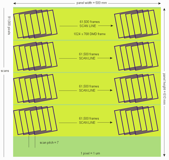
Number of Frames =  [ 500,000 pixels - 69376 (first frame)]/7 pixels/frame = 61,518 frames

How Many Scan Lines?

Again this will depend on any overlap between scan lines. Let's assume there is little overlap - we will assume that the line pitch is 90,868 pixels. If our panel is 610 mm tall then the number of scan lines needed is:

 610,000 / 90,868 = 6.7 = 7

So we need 7 scans to cover the board at a minimum.

number of scan lines and frame count for dmd scan of panel

Time to Extract the Frame Data

Here is where the implication of all these calculations comes in. Basically one needs to load 5.7 GByte of bitmap data into memory and then compute 61,500 frames per scan line. This is a lot of bit shifting. Unfortunately our memory footprint is so large that the bits we need to access to compute each frame don't fit into the local CPU memory cache. This means it takes a lot more CPU cycles to do our computations.

A prototype program we wrote to do this kind of frame extraction seems to produce about 150 frames per second (XGVA) and even less if the DMD is an HD one since the larger frame size requires even more memory.

At that rate extracting the 61.5K frames for a single scan across the panel will take 410 seconds; 7 such scan lines will take a total of 47 minutes!

Since it only takes 3 to 5 minutes to produce the 37 GByte (before compression) bitmap for the panel we see that the frame extraction is a serious bottleneck if done on a conventional workstation.


How to Increase the DMD Frame Computation Rate

Our attempts at using a workstation CPU to convert from a regular bitmap into a series of rotated frames shows that this can be a serious bottleneck for large area, high resolution masks. Assuming this throughput is not acceptable one could build some dedicated hardware to greatly accelerate the process. However, designing and building such hardware in relatively low quantities is extremely expensive.

We decided to examine whether today's modern GPUs might be adapted to speeding up the process. An extremely powerful graphics GPU can be purchased these days for between $300 and $500.

First Results of using GPU for DMD Frame Extraction


Links


Industry Players References and Papers Hardware and Software Solutions