Reversals, Margins, Borders and Extents
The InkRaster program gives the user a number of interacting arguments that control: polarity of the bitmap, margins around the digitized data, a border around the data (and color of the border.) We'll examine how these work and affect each other.
Starting With Our Data
We'll start with our Gerber file called narrow_line.gbr as shown below.
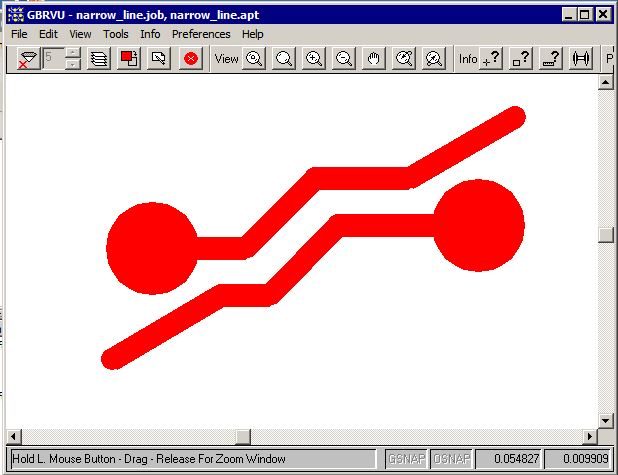
This appears to be a couple of PCB traces and pads. In the normal case we would want to "cover" the digitized data with ink so that when the PCB is etched, the area covered by ink is protected and remains once the photo-resist is washed away.
Now the data extents is computed by the rasterizer and in this case it would be:
inkraster64.exe narrow_line.gbr -out:extents -workdir:working -extent

extents.txt
0.080000 -0.025000 1.910000 1.115000 MM
Now if we generate a bitmap from this data at 2540 DPI then the bitmap size should be 183 pixels by 114 pixels.
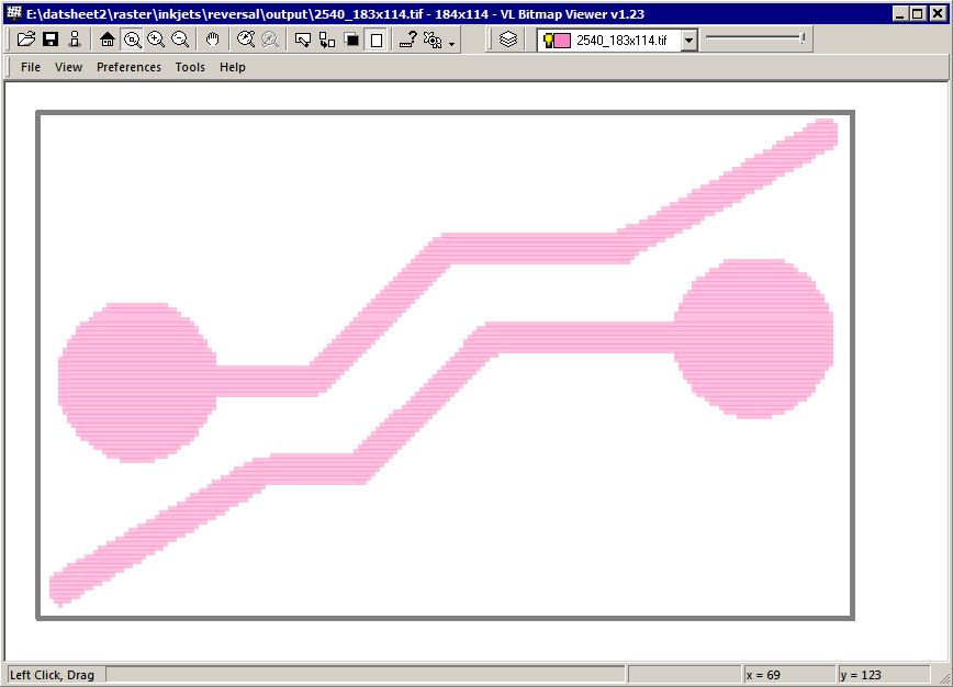
What we actually get when we run this is 184 x 114. The extra pixel is present because the program outputs data byte aligned and 184 is exactly 23 bytes.
Margins and Borders
Now if one needs additional pixels around the extents of the digitized data one can select either the -margin argument or the -border argument or both.
What's the difference?
The -margin has the effect of increasing the data extents computation. The -border extends out the bitmap.
Adding a Black Border
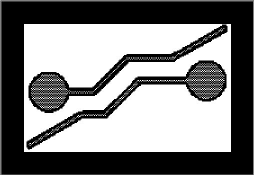
If I decide to add a black border of 20 pixels all around my data I would use the following command line argument (and let's assume we have set our fill coverage = 0.5)-border:20px,fill
And your results would look like this:
Adding a Black Border and a Margin
Now let's say that we think the black border is a bit too close to the digitized data for comfort? Let's add a little bit of margin around the digitized data as a buffer.
Now the margin can only be expressed in input units - in this case MM. So let's add a margin of 0.1 mm all around.
-border:20px,fill -margin:0.1
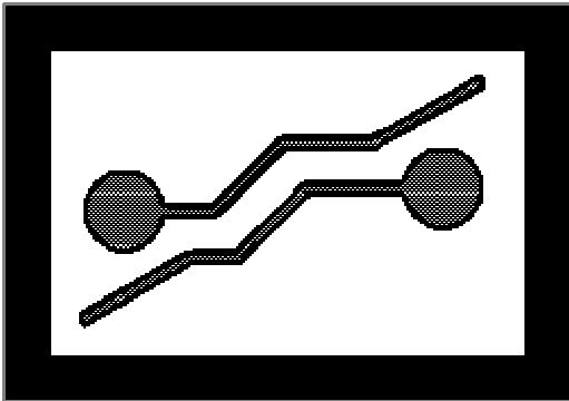
Of course, if your border is "white" then it matters not whether you use the border argument, the margin argument or both. But things change when you decide you need a reversal which we will cover next.
Reversal for Chemical Milling Applications
In the chemical milling industry it is quite common for the designer to digitize the regions to be etched away which is just the opposite of what is done in the PCB industry.
In such a case, the ink has to be deposited everywhere except the digitized area.
So how does the rasterizer deal with this issue?
Answer - it uses a Boolean routine to reverse the digitized data. Part of this routine requires some sort of a bounding box. The bounding box can be generated in different ways.
- compute the extents of the data and use that as a bounding box
- let the user define a window to use as the bounding box.
- compute the extents and add some user defined margins.
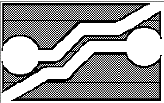
Case A - Extents
Let's run a reversal using just the data extents. We're setting the fill coverage = 0.5 and I'm upping the DPI to 5080 to get a nicer picture.
c:\wcad\inkraster64\inkraster64.exe
%CD%\narrow_line.gbr
-out:%CD%\output\reversal1.tif
-workdir:%CD%\working
-dpi:5080
-droplet:40um
-coverage:0.5,1
-compensate:1,0.5
-reversal
Reversal With Margin
While our output is correct, you can see that the lack of spacing between the bounding box and the digitized data is a problem. So let's add a margin to the reversal of 0.2 mm.
c:\wcad\inkraster64\inkraster64.exe
%CD%\narrow_line.gbr
-out:%CD%\output\reversal1.tif
-workdir:%CD%\working
-dpi:5080
-droplet:40um
-coverage:0.5,1
-compensate:1,0.5
-reversal
-margin:0.2
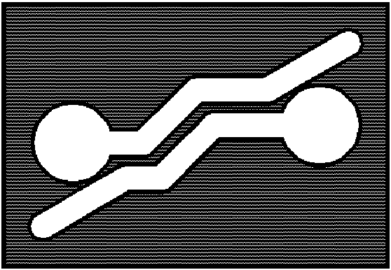
Now that is much better.
A few things to note:
User control of edge and fill coverage is still available
The droplet diameter is correctly taken into account so that the final opening matches the CAD data
The so called "field" area has the reduced ink coverage as specified by the fill parameter. The only issue is the small outer margin which is treated by the program as if it were an edge that should use the edge coverage parameter.
