When converting from GDSII to DXF several features are important: the ability to quickly determine the list of structures in the stream file, the list of data that have layers and the units of the file.
GDS2DXF quickly scans the entire file and presents the user with a complete list of structures including a hierarchy tree. It also presents the user with a list of layers containing data.
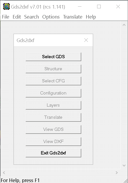
The control dialog takes the user through the steps to make a GDSII to DXF conversion.
First a GDSII file is selected.
Then the structure to convert is selected. Normally this will be the top level structure but need not be.
Next the user opens (or creates) a configuration file and sets the parameters for the conversion.
The user defines which layers to convert and their names in the DXF file.
Finally the Translate button runs the conversion.
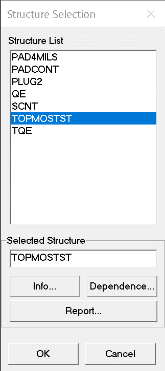
Scroll through the entire list of structures and click on the one you want to translate. The program suggests the top level structure for you based on the number of references.
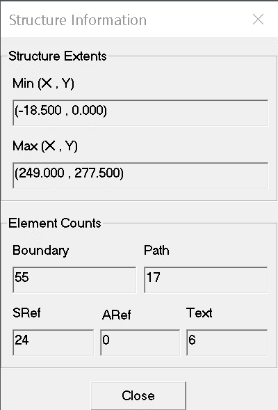
Info... clicking on this button opens a window that summarizes information about the structure that has been highlighted.
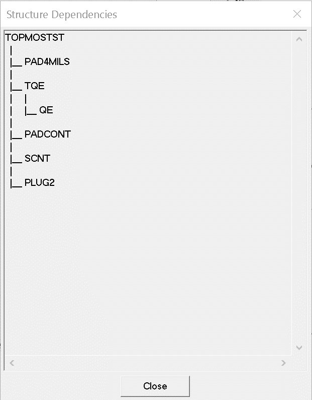
Dependence ... displays a dependence tree for the highlighted structure.
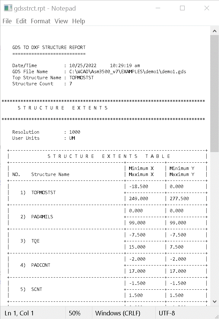
Report... generates a text report on the file.
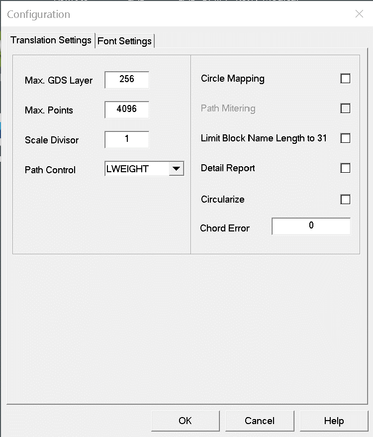
The Configuration Translation Settings tab gives the user control over the output.
Special controls include:
circle mappping - polygons in GDSII that have more than 20 sides and all angles equal can be mapped to DXF circles. This makes the resulting DXF data smaller and smoother.
path mitering - paths that bend sharply (more than 90 degrees) will have their corner mitered when converted to outlines (assuming Path control = OUTLINE)
Circularize - GDSII boundaries where the edge could be approximated as an arc will be converted into DXF arcs (depending on the value of the Chord Error)
Chord Error - a parameter that determines how closely a series of segments can be approximated (and replaced) by an arc in DXF. (In GDSII units)
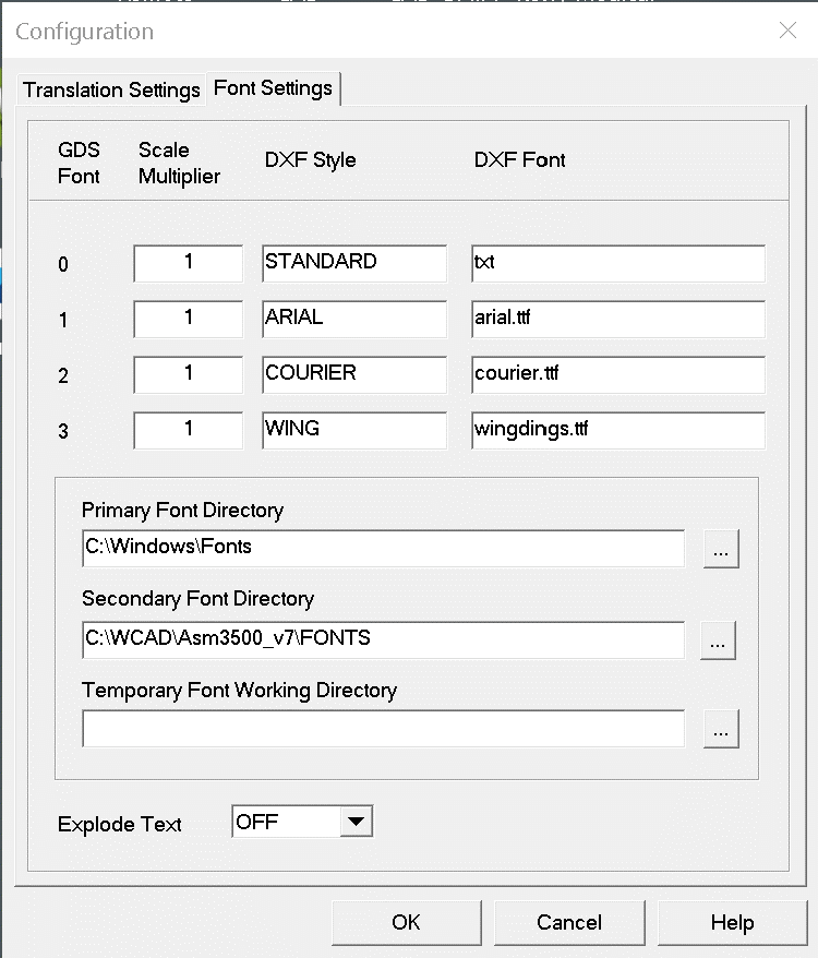
The Configuration Font Settings tab gives the user control over convertsion from GDSII text to DXF text.
Each of the four GDSII fonts can be mapped to an AutoCAD DXF STYLE and DXF Font. Fonts can be of type TTF or SHX.
Explode Text - if selected, instead of inserting a string of text in the DXF file, the text is exploded into polyline using the specified DXF font.
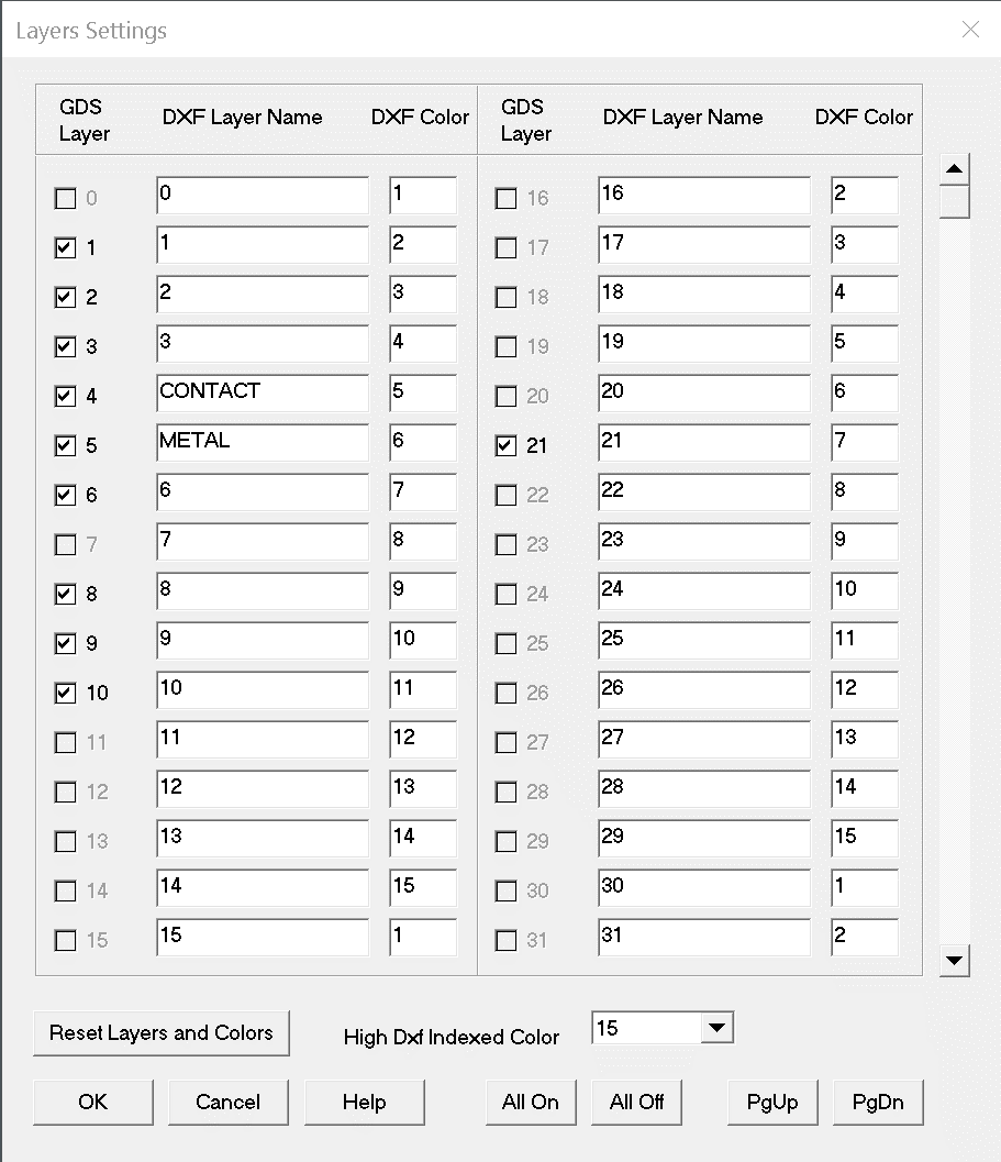
The Layer Settings dialog enables you to select layers for translation quickly - check off layers you want. Easily control the mapping from GDSII layer number to DXF layer name.
It is legal to map multiple GDSII layers into the same DXF layer.
There is no datatype control from this dialog window.
