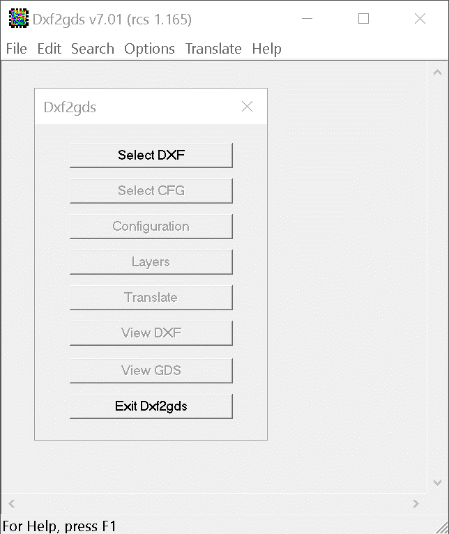
The DXF2GDS control dialog takes the user through the various steps required to convert from DXF to GDSII stream.
First, select the file to convert; then either select or create a new configuration file and edit it (using the dialogs) as needed; then select the layers to convert. Finally press Translate and your new GDSII file is created.
The View DXF button can be linked to your AutoCAD (or other CAD executable) to view the DXF file you have selected.
The View GDS button automatically passes your newly created GDSII file to our GDSII viewer.

This dialog box shows the various settings for translation. Values are saved in the registry - the next time you run the program your previous settings are recalled.
The Translator Tab
If needed the DXF file can be scaled to different units; the maximum number of vertices in a boundary can be set as well as the maximum layer number for the GDSII file.
The user can force zero width entities such as lines into a GDSII path with a minumum width.
Line/Arc linking can be enabled.
AutoCAD polylines with width can be forced to convert to GDSII boundaries.
De-embedding option (license required) can be used to sort and convert drawings with nested polygons.

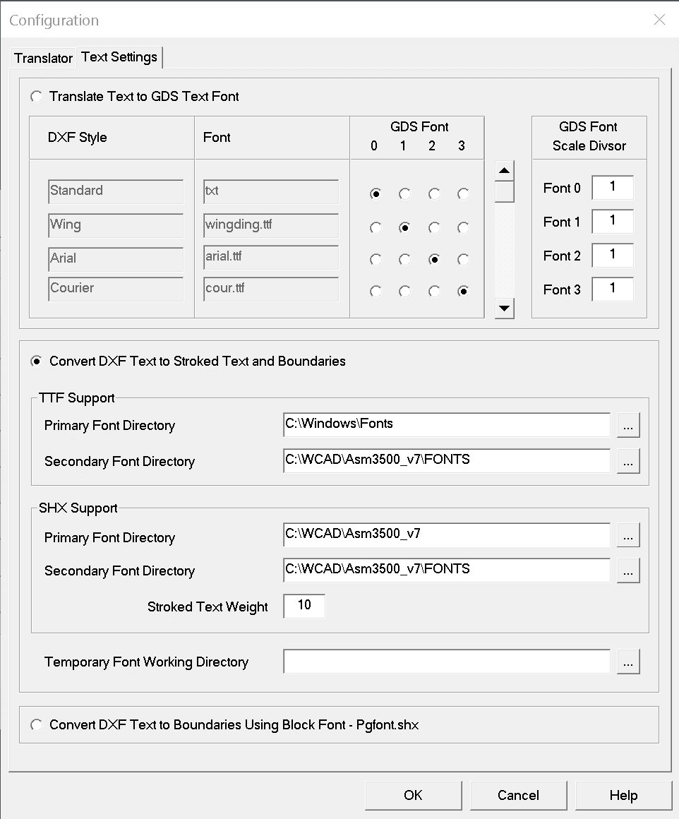
The Text Settings Tab
The user controls how text is converted using this tab. User can translate DXF Text to GDSII Text. The user can also opt to convert the DXF text into GDSII strokes or boundaries depending on the DXF text's font.
Details here

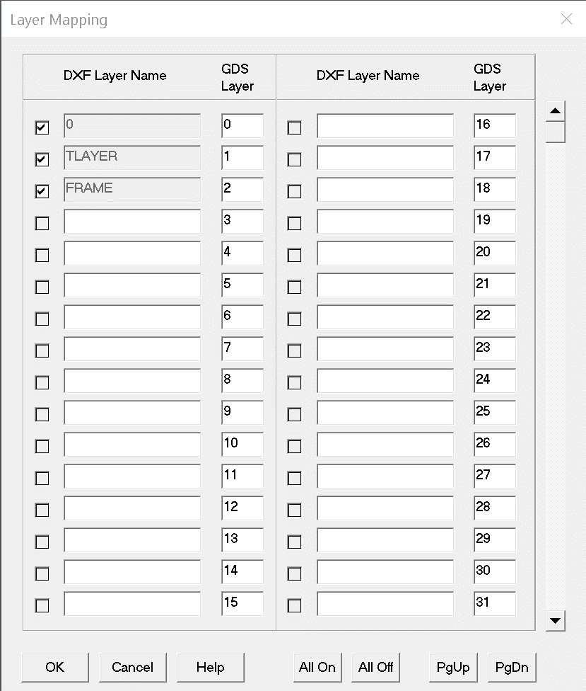
The DXF2GDS layer menu enables you to quickly select desired layers to translate and to set layer names to GDSII layer numbers.
