
For the examples we are going to use the GDSII file, test_panel.gds, where we have a panel with 6 circuits. We've also added a box to define where we want our bitmap -- a QR Code -- to be placed. The file includes a construction layer so we can easily view the coordinates of the box locations.
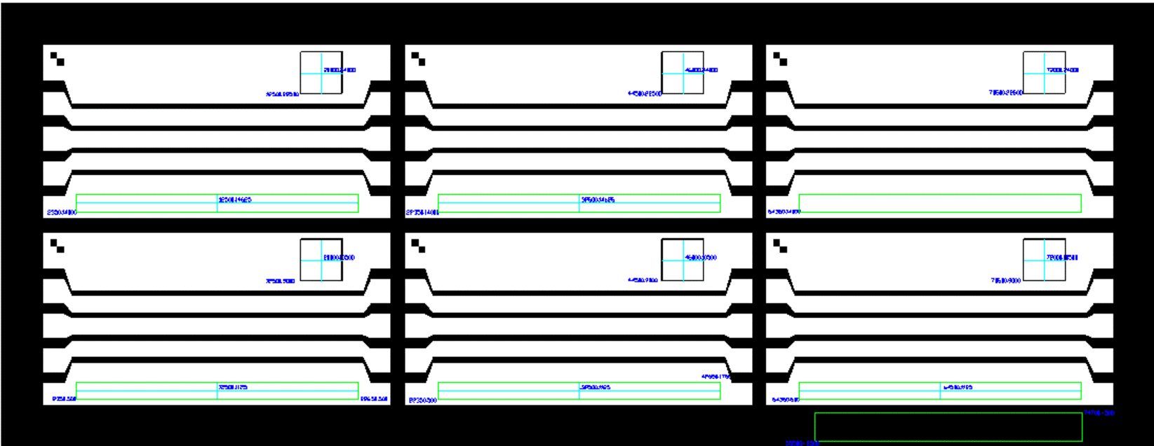
Figure 1 - test_panel.gds used for bitmap annotation examples.
We will focus on the two circuits in the top row of the panel starting in the upper left.
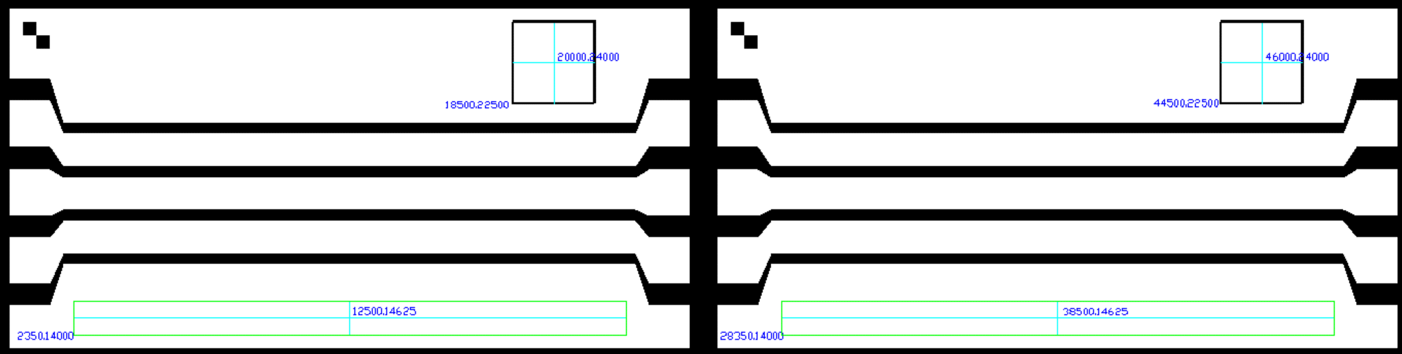
Figure 2 - Upper left circuit with box for QR Code.
In this example we will insert the same bitmap in two locations. On the left circuit we will use the lower left coordinate of the box as our insertion point; on the right circuit we will use the center of t he box as our insertaion point.
We are not showing the GLOBAL section except to note that we set the pixel size to 70.7 um and that the bitmap is 56x49 pixels in size.
# Example 1: insert at lower left of box

B_BITMAP

BITMAP part_no_0_1.raw

SCALE 1.0

XY 18500 22500

E_BITMAP
# Example 1b: insert at center of box

B_BITMAP

BITMAP part_no_0_1.raw

SCALE 1.0

XY 46000 24000

E_BITMAP
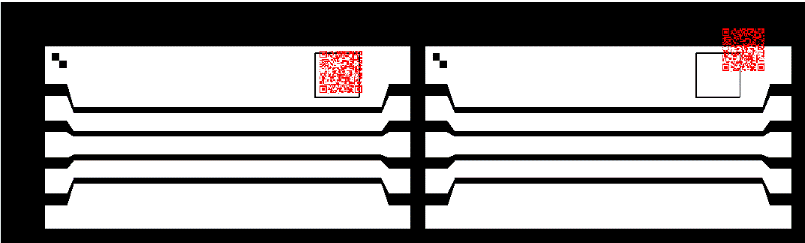
Figure 3 - Results of Example 1
Notice that although we made very careful computations, our bitmap is not positioned exactly where we want it. It seems shifted a bit right and upward of the insertion point. Why?
Well it has to do with the bitmap we are using. Although we can measure the visible portion of the bitmap at 41 x 41 pixels, the actual bitmap size is 56 x 49. There are some "empty" pixels acting as a margin around the bitmap. Unless the user knows this and then compensates for the empty margin pixels, the placement will be off.
Since there are 4 pixels left and below the QR code, we should offset our insertion point by 4 x 70.7 or 283 um.
We also have to account for the pixel size so we need to reduce the offset by 1/2 pixel, or 35 um. This brings the offset to 248 um.

Figure 4 - empty pixels surrounding the QR code.
So let's repeat the bitmap insertion but account for the extra 248 um.
# Example 1: insert at lower left of box

B_BITMAP

BITMAP part_no_0_1.raw

SCALE 1.0

XY 18252 22252

E_BITMAP
# Example 1b: insert at center of box
f
B_BITMAP

BITMAP part_no_0_1.raw

SCALE 1.0

XY 45752 23752

E_BITMAP
And you can see that the placement is now spot on.

The lesson here? If at all possible, make sure your bitmap is cropped to just the exact size containing the data you want to place. Any margins will require careful offset correction computations.