
|
Program Operation |
The Configuration Dialog Window
|
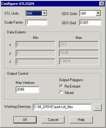
STL Units - the STL file does not include units in the header so the user has to know and select from the usual choices. GDS Units - select from: UM,MM,CM, NM, INCH, MIL The program takes into account any scaling needed by changing the input and output units. GDS Grid - the grid value determines the resolution of the GDSII data - i.e. 0.001 is typical for units of microns. Scale Factor - the user may need to scale the input data. If so, he can enter a value here. Default = 1.000 of course. Data Extents - the min and max extents for x,y,z are shown here based on a scan of the input file. This helps the user as a sanity check; if the extents are different than what he is expecting he can act on it prior to running the conversion. Extents are calculated prior to scaling. |
|
Output Control Max Vertices - the maximum number of vertices allowed per boundary. The official GDSII spec is 200 but many tools can read up to 2048 vertices per boundary. Output Polgyons - choose between Re-Entrant (also known as Cut Lines) and Sliced. Working Directory - a directory specified by the user where temporary and intermediate results are written and where the log file is written. |
| Program Operation: 1 | 2 | 3 | 4 | 5 |
| STL2GDS Home Page | Download | Revision History | Price |
|
|