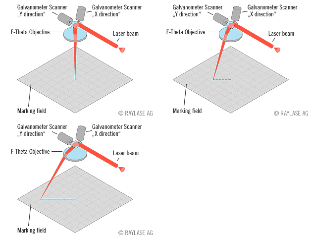
IntroductionDrl2lsr is a program which reads Excellon formatted drill files and converts them into a specialized format optimized for UV and CO2 laser drillers. Because lasers are only deflectable over a small distance, the program divides the extents of the substrate into user defined windows. The program then recomputes the coordinates of each drill belonging to a window with respect to the center of the window. Finally it sorts the drill order within each window to minimize the "travel" or deflections needed to populate the window. The order of the windows are also sorted into a serpentine path. The net result is a file that can drive the laser drilling machine as efficiently as possible. |
|
Excellon Drill InputDrill files look fairly similar to Gerber files -- they both have CNC code as their basis, but drill files may include additional commands about feed rates and other items that don't apply in Gerber. When reading a drill file the program must take into account many real world details. These include: Undefined Tool Size - while the drill format includes the ability to define a tool's diameter, such information is not always included. The user has to manually enter the correct diameter. Units - Drill files are either in units of inches or mm. However the actual unit identification may or may not be present in the drill file. Zero Suppression - often either leading or trailing zeros are suppressed to make the file smaller. However this information must be provided to the drill2gbr program so that it knows from which side of the value to re-insert the decimal point. Mode - data can be absolute or coordinates can be expressed relative to the previous location. Format - Since the decimal point is normally suppressed, the program has to know where to re-insert the decimal point. This information is not present in the header. The format 2.4 Since the program cannot always determine the correct parameter settings, it is the user's responsibility to enter the correct parameters. Command LineThe drl2lsr.exe program is driven by a command line. The syntax is shown below: drl2lsr.exe [inut_file] [options] output options -out:<output_basename> specify the output file base name -units:<units> specify inch or mm for output file if not specified, output units will match input units. -roi:<minx,miny,maxx,maxy> Specify the RIO (region of interest) to process. If not specified the program will compute data extents. -offsetx:<x_value> offset the input data in X by the specified amount. -offsety:<y_value> offset the input data in Y by the specified amount. -scanwindow:<w,h> specify the window dimensions. If not specified the default is 50 x 50 mm. -margin:<w,h> specify a margin to be added to the specified ROI. -laser Output a laser file. -gbr specify output as Gerber (for debugging) -log:<log_file_name> specify the name of the log file -scan:<scan_file> just scan the input and generate a scan file overrides -laser and -gbr -silence run in silent mode. [input options] -drlunits:<units> specify drill file units. (inch or mm) -drlformat:<spec> specify the data format i.e. 2.4, 3.3 -drlzeroinc<inc> specify zero inclusion: leading, trailing or decimal -drlxymode<mode> specify input mode: absolute or relative -list:<list_file> get list of drill files to process from file -map:<map_file> specify map file to read for user mapped d-codes to tool numbers. |
Example 1The drill file, viapattern-via52.txt, needs to be converted to laser format. Upon opening the file in a text editor we can examine the first few lines: G48 T01C.0080 % G92X000000Y000000 G80 X000000Y000000 T01 G81 X-029803Y-015022 X-029646 X-029803Y-014663 We can see that there is only one tool (T01) with a diameter of 0.008. We see that leading zeros are included, and based on our experience and examining the data we know that the format is 2.4. We are going to use units of inches because the coordinates and drill diameter make no sense in mm. Therefore our command line should be: c:\wcad\drl2lsr\drl2lsr.exe <-- the conversion engine viapattern-via52.txt <-- the drill file to convert -drlunits:inch <-- units of the drill file -drlformat:2.4 <-- data format of drill coords -drlzeroinc:leading <-- zero inclusion parameter -drlxymode:absolute <-- coordinate mode parameter -laser <-- output laser file -out:via <-- output file base name -log:via.log <-- log file Results The conversion is completed in a second. Two files are produced: via.lsr (the laser file output) and via.log, the log file. The via.lsr output looks like: M48 INCH, LZ ;SOURCE FILE: viapattern-via52.txt ;DATE: Wed Aug 26 13:31:07 2015 ;SCAN SIZE: X=1.9685, Y=1.9685 T1C0.0080 M95 T1 BLOCK0_0 X-1.9961Y-2.0534 U-0.6171V-0.9664 U-0.5818V-0.9664 U-0.5462V-0.9664 The log file includes useful information: rill2Laser Drill Converter v1.0 rcs 1.102 (2015/08/26) (C) 2015 Artwork Conversion Software, Inc. (831) 426-6163 info@artwork.com, www.artwork.com Input Drill File Info: -Units:Inch -Format:2.4 Output Info: -Units:Inch ROI Window: -2.9803, -3.0376, 2.9803, 3.0376 Tile Width: 1.9685 Tile Height:1.9685 Margin Width: 0.0000 Margin Height:0.0000 Calculating Block Extents ... Total Blocks: 16 (4 x 4) Block Extents: Block [0_0]: -29803, -30376, -10118, -10691 Block [1_0]: -10118, -30376, 9567, -10691 Block [2_0]: 9567, -30376, 29252, -10691 |