 |
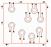
Geometry OptionsNETEX-G processes polygons (boundaries). All other Gerber geometry is reduced to these entities during the boolean process. For islands surrounded by areas of metal we have found it necessary to offer several different options depending on what the next software needs to receive. Consider the simple ground plane shown below. It consists of a rectangular region containing several round "islands". These islands represent via clearances in the design. The question arises: from a simple collection of polygons how do you describe this configuration? 
One constraint that we must always follow: All polygons must be simply connected -- i.e. one should be able to go from any point in the interior to any other point in the interior without crossing and edge of the polygon. |
Cut Line OptionA cut line is a path into and out of a polygon that enables the user to surround an island. This approach is commonly found in the IC industry and can be used to create a polygon with any number of islands in it. A polygon with a cut line meets the simple connected rule. It is often referred to as a re-entrant polygon. Disadvantages include: the polygon can get very complex and vertex count increases to the point where many operations become slow; many CAD systems fail to process such polygons. For example, if you create such a polygon, export it to AutoCAD as a polyline and attempt to extrude it into a 3D solid, AutoCAD will not be able to extrude it. |

|
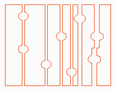
No Cut Lines (Butting)A second option is to break the polygon into several smaller ones that do not require an island. Instead, they butt up against one another in a way that forms the island between two or more polygons. Disadvantages include: one loses the concept of one polygon per net; most finite element programs will generate an unecessarily large number of facets where the polygons abut. The polygons show at right are slightly shifted so that you can see the boundaries. |

|
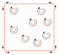
Leonov PolygonsA Leonov "polygon" consists of a set of polygons -- a container polygon and one or more children. The rules are: One container polygon whose boundary is described in the CCW direction. One or more children polygon(s) whose boundary is described in the CW direction and who also must not: intersect each other or intersect the container boundary. This description tends to be the most compact approach and if the finite element tools can support it will result in the most efficient analysis. |

|
Download |
Benchmark Files |
Revision History |
Price |
|
|