For some applications, NETEX-G does not need to "know" the profile or outline of the PCB or package data it is processing. However there are many applications when NETEX-G needs to have a profile or bounding box if it is to correctly perform certain Boolean functions.
What are these conditions?
If the user wishes to process only a small window of the overall data
If there are input files that require reversal such as solder masks or power planes.
If output of NETEX-G is to be used to create 3D model of the PCB.

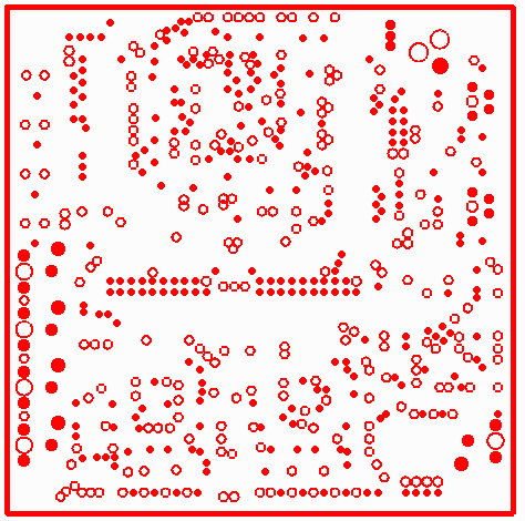
Figure 1: an internal power plane - the data must be reversed to get the correct metal pattern for net tracing or for 3D modeling.
To compute a profile the command line option -genprofile must be used.
-genprofile
The -genprofile argument must then be accompanied by additional arguments.
-prfselwin:<value>
This must accompany -genprofile on the command line and tells the netexgmgr how to generate the profile. It has three possible values:
dataexts - if this argument is used, the netexgmr will scan the input data files (only the conductor layers) and find the min and max X and Y values. These will be used to create a profile in the shape of a rectangle. Note: this method is not 100% reliable if the input data uses custom flashes because the program does not evaluate the "size" of a custom flash; only its center point. If a custom flash defines one of the min or max edges the program only uses the center coordinates of the custom flash and may produce a profile that is too small.
window - if this argument is used, the engine expects to read a rectangular window from an argument called -roi_window.
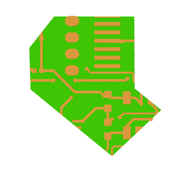
poly - if this argument is used, the engine expects to read a polygonal region. The polygon definition is found by reading another command line argument called -roi_polywin: which "points" to a file containing details about the polygon.
File Syntax for the Polygon
<unit>                    if present, determines units of the coordinates.
1                         number of polygons
8                         number of vertices
-0.163900    2.053000     first vertex
0.079000     2.053000     vertex
0.079900     1.833900     vertex
0.160500     1.768400     vertex
0.011600     1.628000     vertex
-0.235100    1.831000     vertex
-0.238900    1.957200     vertex
-0.163900    2.053000     last vertex (same coordinate as first vertex)

A section of PCB cut out by NETEX-G by defining a polygonal ROI.
-roi_window:
If prfselwin:window is used then -roi_window: must also be present as it defines the lower left and upper right corners of the window. The units are in the input data units - and since our input data is Gerber, this means either inches or mm. [Update] User is able to override the default units by specifying them on the command line.
-roi_margin:
If prfselwin:dataexts is used then -roi_margin may also be used as it defines an additional margin to be added to the extents computation. We recommend a small value here so that when doing the Boolean reversal there is less likelihood of slivers or tiny illegal polygons at the edges of the reversal window. This command line argument is ignored if prfselwin:window or prfselwin:poly is in effect.
In this example, we are creating the profile based on the data extents and with no additional margins. I've put some carriage returns in the example below to make things more clear but there are none in the actual command
"C:\wcad\netex-g\artwork\netexgmgr.exe"
"C:\wcad\netex-g\EXAMPLES\odb_input\work\pcbdata.njb"
"C:\wcad\netex-g\EXAMPLES\odb_input\out\sample_auto_0.3di"

"-wdir:C:\wcad\netex-g\EXAMPLES\odb_input\work\"

-loutput
-maxpts:64000
-arcres:45.000000
-arcsag:0.000010
-omit_extracts
-outtype:3di
-dielectric_profile

-silent
-thrnum:4
-drillarcres:45
-drillarcsag:1e-005
-circularize

-genprofile
-prfselwin:dataexts
-roi_margin:0
In the second example, we are creating the profile based on a window defined by lower left and upper right with no additional margins.
"C:\wcad\netex-g\artwork\netexgmgr.exe"
"C:\wcad\netex-g\EXAMPLES\odb_input\work\pcbdata.njb"
"C:\wcad\netex-g\EXAMPLES\odb_input\out\sample_auto_0.3di"
"-wdir:C:\wcad\netex-g\EXAMPLES\odb_input\work\"
-loutput
-maxpts:64000
-arcres:45.000000
-arcsag:0.000010
-omit_extracts
 -outtype:3di
-dielectric_profile

-silent
-thrnum:4
-drillarcres:45
-drillarcsag:1e-005
-circularize

-genprofile
-prfselwin:window
-roi_window:-0.135406,-0.069284,4.335283,2.166061
-roi_margin:0
In the third example, we are creating the profile based on a polygon. The points defining the polygon are defined in a text file roi_polywin.txt, with no additional margins.
"C:\wcad\netex-g\artwork\netexgmgr.exe"
"C:\wcad\netex-g\EXAMPLES\odb_input\work\pcbdata.njb"
"C:\wcad\netex-g\EXAMPLES\odb_input\out\sample_auto_0.3di"

"-wdir:C:\wcad\netex-g\EXAMPLES\odb_input\work\"
-loutput
-maxpts:64000
-arcres:45.000000
-arcsag:0.000010
-omit_extracts
-outtype:3di
-dielectric_profile

-silent
-thrnum:4
-drillarcres:45
-drillarcsag:1e-005
-circularize

-genprofile
-prfselwin:poly
"-roi_polywin:C:\wcad\netex-g\EXAMPLES\odb_input\work\roi_polywin.txt"
-roi_margin:0