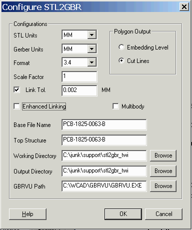

STL Units - the STL file does not include units in the header so the user has to know and select from the usual choices.
Gerber Units - select from: MM or INCH
Format - precision and range of Gerber Data. Typical for MM would be 3.3 and for INCH 3.4
Scale Factor - the user may need to scale the input data. If so, he can enter a value here. Default = 1.000 of course.
Link Tolerance - When STL is exported from a 3D CAD program there are small numerical errors in the coordinates of the triangles that define the body surfaces. By adjusting the link tolerance the program can often overcome these errors. The ideal value for such files can only be determined by trial and error since the numerical noise and its effect on the proper linking of the triangles is variable.
Polygon Output
Embedding Level - islands are generated using Gerber's LPD/LPC command. As many LPD/LPC layers are generated as needed to handle the polarity changes.
Cut Lines - islands are formed using cut lines - these are figure edges which enter and exit the figure and wind around the island area.
Enhanced Linking - This option handles special situations when a decision should be taken on which path to link, the situation being when multiple paths intersect within a vicinity of a given point. The criteria is to choose the connecting path which results in the least amount of change in direction. Without this argument, it just chooses the first one found..
MultiBody - Intersecting surfaces are unionized. This also allows path linking to be done independent of the -grid:G argument. Typically you will leave this option off.
Base File Name - multiple Gerber files may be created depending on the number of slices. Each Gerber file is named using the base file name plus a slice layer index.
Top Structure - this control has no meaning for Gerber - it applies to the GDSII output format only.
Working Directory - a directory specified by the user where temporary and intermediate results are written and where the log file is written.
Output Directory - a directory where the output Gerber files will be written
GBRVU Path - a directory/filename to the GBRVU executable - i.e. "C:\WCAD\GBRVU\gbrvu.exe" This tells STL2GBR how to launch the Gerber viewer.