
|
Program Operation |
The Define Slices Dialog Window
|
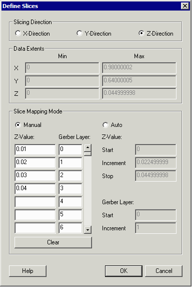
Slicing Direction - depending on which axis your data was extruded, select the correct slicing axis. Data Extents Information - the STL file's extents are shown as an aid to the user so that he does not select a value outside of the body of the structure. It can also provide a hint as to the correct axis to use for slicing. Slice Mapping In Manual Mapping Mode the user defines each slice height manually and maps it to a unique Gerber layer. In Auto Mapping Mode the user defines a Start, Increment and Stop slicing value and the program will calculate the heights for the slices. Gerber Layer - generally the first slice is mapped to layer _0 but a user may wish to control both the starting layer and the layer name increment ... |

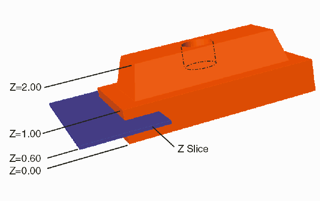
It is clear from this 3D perspsective view that the mask results depend on the Z-slice height. For slices from 0 to 1 mm the mask is identical. But once the Z value rises above 1.0 the mask will vary due to the taper of the top isohedron. The hole bored into the top (0.5 mm deep) will also affect any masks where Z > 1.5. |
| Program Operation: 1 | 2 | 3 | 4 | 5 |
| STL2GBR Home Page | Download | Revision History | Price |