apd_title.gif
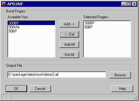
Artwork has developed a SKILL based interface to Cadence Advanced Package designer. This allows the package designer to easily create an AIF file directly from within APD. To generate the AIF file use the new APD2AIF menu item on APD's main toolbar and click on Export AIF.

apd2aif4.gif


APD2AIF Dialog Box

apd2aif2.gif The designer needs to specify which vias are used for bond fingers and ring attach. (If in doubt, it is better to specify additional vias than to leave one out....)
Writing the AIF File
You can select the directory and the filename for your AIF file. The file is a simple ASCII file and can be moved across UNIX/Windows machines and across networks without problems. Hit OK when you are ready to write the output.


Minimum Design Requirements

AIFOUT searches the APD database for

  • Two Components
      There must be two components: a die and a package. AIF out was not intended to handle multiple die. NEW - AIFOUT Version 1.04 updated to support multiple die!

  • Die Component
      Die pads are defined as pins in the die component. These pins should be labeled with integer numbers 1,2,3.... A square, round or rectangular padstack should be assigned to the pins. You can have different sized/shaped pins as needed i.e. not all pins need be assigned to the same padstack.

  • BGA Component
      Land Pads (Balls) are defined as pins in this component. These pins should be labeled with the JEDEC assignment such as A1, F5, AA25. Pins should be assigned a round, square or rectangular padstack.

  • Bond Fingers
      Bond Fingers should be vias. They cannot be pins inside of either the die or the bga component. They should be assigned to a padstack such as rectangle or oblong or round.

      When attaching to a ring, use a different via/padstack than for regular bond fingers. Normally this is a circle/round of the same diameter as the wire.

      You need not label the bond fingers as BONDGEN can do this for you very quickly and automatically in AutoCAD.

  • Padstacks
      Padstacks used for fingers, die pads and lands should have the same geometry on all subclasses. i.e. if the padstack is defined as a .025 mm round on class conductor/subclass wirebond it should also be 0.025 mm round on class conductor/subclass top.
  • Power and Ground Rings
      Power and ground rings are extracted on the following basis:

        They must be a shape on a conductor class
        there must be some connection to a die pad via a wire. Other shapes are not extracted.
  • Documentation

    Encore Data Sheet       PDF Document (408 KB)

    APD Data Sheet           PDF Document (373 KB)


    Bondgen Home Install for Encore Install for APD Price Download Rev History