web_page_logo.gif


Introduction

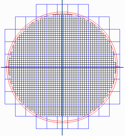
Reticle Shot maps are often provided by a foundry to a packaging or test vendor in order to help the vendor located the precise locations of the die on the wafer

Our particular interest in shot maps is to create a template for the designer of RDL or other package on wafer masks.

It is important that the RDL whole wafer masks align precisely with the die that have already been fabricated on the wafer and that the center of the mask and the center of the wafer are precisely aligned.

  reticle_map.gif


How the Foundry Provides the Die Locations

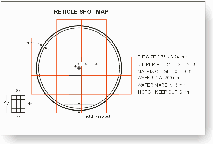
One would think that the foundry could provide the exact center of each die in some kind of a tabular format with X,Y coordinates. However we have found this to be rare. Instead the foundry often generates a report (or even a screen shot) from their stepper control software. For example, a typical stepper report is shown below:

typical_shot_map_from_foundry.gif

It is the responsibility of the RDL mask designer to take these parameters and to convert them into a layout in order to know exactly where each die is placed. RMapGen simply automates this process.

The results from RMapGen are then combined with a layout generated from a wafer map (which has additional information about knocked out die and alignment/test die) to create a final layout that includes the exact positions along with precise identification of each die.


How it RmapGen Works

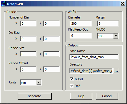
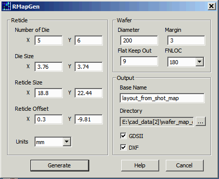
The user starts up the program and is presented with the main dialog
rmap1.gif

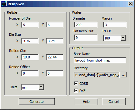
Typically the number of die in the reticle is provided along with the die "size." The size could also be the stepping distance of the die within the reticle. Set the units. Typically this will be either mm or um. Enter those two values and the program will compute the reticle "size."
rmap2.gif

Now enter in the offset. This is the amount that the "center" reticle shot is offset from the center of the wafer.
rmap3.gif

Wafer Information

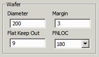
Enter the wafer diameter and the margin.
rmap4.gif

The program will only generate die if they fall inside of the margin and also inside of the line defined by the Flat Keep out parameter:

notch_keep_out.gif

Output Information

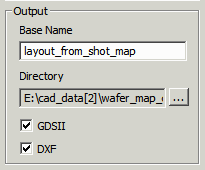
Enter the base name for the GDSII or DXF file. Also enter the directory where you want the output files to be placed. Finally, check either DXF or GDSII (or both) to tell the program which layout formats to produce.
rmap5.gif

Now press the Generate button and your layout file will be created.


Layout File Organization

Data is organized by hierarchy and by layer. Go here to see the details ....


Download Revision History Video Tutorials Price