For a calling application to run Gerber Union it must generate the correct command line and launch the gbrunmgr.exe or gbrunmgr64.exe (GerberUnion Manager) program. Syntax is shown below:
gbrunmgr64.exe
         input_gbr
                   -out:output_file
                                      -wdir:dir
                                                 -outputtype:type
                                                                    [options]

where

gbrunmgr64.exe              path/name of the Gerber Union Manager executable

input_gbr            path/name of the input Gerber (RS274X) file

-out:output_file     path and name of the output file.

-wdir:wdir           the directory where working and temporary files are written.

-outputtype:type     The type of output. Possible outputs: (may require license)
                     [rs274x | dxf | gds_stream | gds_cshape | egs]


[options]

Data Polarity Controls
=======================

-emblevel                 Generates embedding level output.  This
                          format represents holes by assigning a
                          layer to a level of embedding.


-polyformat:pftype        Indicates method for representing holes in
                          polygons other than embedding level.
                          pftype is [leonov | cutlines | butting]
                          Default is cutlines.


-reversal:x,y             Generate a reverse image of unionized output.
                          x is for left and right margins extending
                          from data extents or output window.
                          y is same as x but is for top and bottom
                          margins.


Data Transformation Controls
============================

-xform:<xform_parms>      transformation settings (comma separated) in this order:

                          rotation_parms, mirror_parms, scale_parms, offset_parms

  rotation_parms          anchor_x[<units>],anchor_y[<units>],rotation

  mirror_parms            N,M where N=1 flags mirror_x M=1 flags mirror_y

  scale_parms             scale_x,scale_y

  offset_parms            offset_x[<unit>],offset_y[<unit>]

                          unit: INCH | MIL |CM | MM | UM
                          if the unit modifier is absent, the program assumes
                          the units of the incoming Gerber file.

                          order of operation: rotation, mirror, scale, offset
                          angles increase in CCW direction

                          see the transform page for examples.


Gerber Output Controls
========================

-aptin:apt_file           Specify  as aperture file to be used to format RS274d files into RS274X.

-no_g36                   Outputs Gerber trace output instead of
                          area fill polygons  w/ G36/G36 codes.

-dcode:number             Specifies number for dcode to be used for trace output.

-dcode_lpc:number         Specify number as dcode to use for trace data in %LPC% layers.

-diameter:value           Specifies diameter of round dcode for trace
                          output. See unit control notes.

-diameter_lpc:value[unit] Specify diameter of trace data to replace G36/G37 polygon data in %LPC% layers.
                          unit can be: INCH, MIL, CM, MM, or UM.  No unit implies Gerber input units. (used with -no_g36).

-no_lpx                   Suppress %LPD% and %LPC% layer polarity statements

-fmt[auto|best]           Tells Gerber preconditioner, split274x, to push format
                          to best format, 2.6 inch or 3.5 mm, if -fmtbest is called.
                          Otherwise, it uses auto mode to correct: bad format, mult-defined apt., high dcode. (Default -fmtbest).

-macro_tol:value[unit]	  Set Gerber preconditioner, split274x, macro tolerance
                          into value, used for identifying similar aperture macros.
                          unit can be: INCH, MIL, CM, MM, or UM.  No unit implies Gerber input units.
                          (Default 0.001 MM or 0.00004 Inch).

-mesh_adjust              Handle mesh draws barely touching edges.

-nosplit                  Prevent Gerber preconditioner, split274x, from running.

-bgn_split_args args e_arg   Add additional arguments,to split274x and end these additions with e_arg
                             where e_arg stands for -end_split_args


Data Partitioning
=================

-single_part              Enforce single threaded operation while not invoking
                          manual or auto partitioning.

-joinpart                 Turns on data partition joining.

-manpart                  Specifies that data partitioning is user specified.

-partition_nx:number      Specifies the number of vertical stripes
                          for data partitioning. (used with -manpart).

-partition_ny:number      Specifies the number of horizontal stripes
                          for data partitioning. (used with -manpart).

-autopartrcarray          partitions input into boxed areas instead of stripes.


Geometry Sizing Controls
========================

-engargs -manh                     Use Manhattan sizing. Default: 3 points.

-engargs -fivept                   Use Five point sizing.

-sizingvalue:value        Positive value grows data and negative value shrinks it.


Polygon Clean Up Controls
=========================

-slivervalue:value        Specifies value for removing very thin data.

-smoothingvalue:value     Specifies value for removing consecutive points closer than the value specified.

-dirtydata                Remove sloppy data by growing data slightly and then size to target size.

-usecircbool              Output using circular Boolean.


Output File Units and Scaling
=============================

-useotherunits:unit       Specifies output unit as unit.
                          For Gerber output unit can be [inch | mm].
                          Otherwise, unit can be [inch | mil | mm | cm | um].

-outscale:value           Scales the output by value.

-offset:x,y               Offset output by (x, y).

-outputgrid:value         Specifies value of what output grid the data snaps to.

-maxpoints:number         Specifies maximum number of vertices per polygon.


Arc Controls
============

-arcres:value             Specifies arc resolution for arc data representation.

-arcsag:value             Specifies arc chord error for arc data representation.

-circularize:value        detect line segments describing an arc and convert them
                          back to arcs. The value indicates a chord error
                          tolerance. (Applies to RS274X and DXF output formats)


DXF Output Controls
====================

-basename:layer_substr    Sets   DXF layer names to be of the form: layer_substr_#
                          where # is a number from [1-N]. Default form is L_#


Defining Region to Process
==========================

-window:extents           Clip to window defined by extents which are
                          in the form LLx,LLy,URx,URy.

-polywin:plyfile          Clip to region(s) defined in plyfile.
                          See "Polygon File Format" below.


Messaging Controls
==================

-no_warnings              Prevents warning messages from appearing
                          anywhere except in log file.

-silent                   Silences individual program's progress dialog.

-singledlg                Directs progress information of each
                          executable into a single progress dialog.

Processing and Threads
======================

-passthru                 Will flatten data without unionizing.

-thrnum:thnum             thnum indicates how many threads to use when unionizing.
                          Default is to detect number of CPUs and set the concurrent
                          threads = number of CPUs.

Units on the Command Line
=========================

                         If not specified, dimensional arguments on the command line
                         are in the same units as the input file i.e. either inch
                         or mm.

                         To override the default unit users can follow a dimension
                         value by a unit: um | mm | inch | mil.

                         Example: -sizingvalue:10um


Engine Arguments
=========================

-bgn_gdscomp_args [args]  [e_arg]   Add additional arguments, [args], to gdscompact engine
                                    and end these additions with [e_arg] where [e_arg] stands for -end_gdscomp_args

-engargs [args]                     Add additional arguments, [args], to boolean engine.
                                    This must be placed at the end of the command line.

-bgn_split_args -dcode_adjust:value -end_split_args    Adjust mesh lines by value to ignore small numerical errors.
                                                       Default: value=1um


========= end of options ======================================================
Polygon File Format for Complex Cutouts
Let's say you want to clip one ore more irregular regions to "clip" out of your Gerber input file. One can specify one or more regions using the -polywin:file argument (instead of -window) and creating a file with the correct syntax describing the polygon.
In order to prepare the text file you must know in advance:
a) the number of polygons in your file.
b) the number of vertices in each polygon. The first and last vertex must be on the same coordinate so a square has 5 vertices.
c) the X Y coordinates.
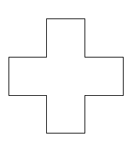
For a single cross shaped cutout our "cross.txt" file looks like the image at right:
1
13
4.66 8
5.33 8
5.33 8.66
6 8.66
6 9.33
5.33 9.33
5.33 10
4.66 10
4.66 9.33
4 9.33
4 8.66
4.66 8.66
4.66 8

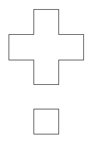
If we had two regions to cut out -- a cross and a square -- then our polywin file "cross_square.txt" file would look like the image at far right:
2
13
4.66 8
5.33 8
5.33 8.66
6 8.66
6 9.33
5.33 9.33
5.33 10
4.66 10
4.66 9.33
4 9.33
4 8.66
4.66 8.66
4.66 8
5
4.66 6.66
5.33 6.66
5.33 7.33
4.66 7.33
4.66 6.66
