In addition to grey scale output, GBR2GREYSCALE can produce a dithered bitmap output.
The reason to use dithering is to improve the uniformity of line width and position after exposure by reducing the effects of pixel snapping. The width and position of a trace may be compromised if the edge of the trace partially overlaps a pixel boundary and the pixel is either discarded or included.
Figure 1: a trace may be shifted due to pixel snapping whenever its edges are not aligned to the pixel grid
One can moderate the effects of snapping by dithering the monochrome output. This is done as follows:
Figure 2: When we supersample (using 4x4 array of subpixels) we have more "information" about the edge location.
The Dither Matrix
For greyscale output, we would count up the number of subpixels that are the "black" and then compute the percentage black for the array of subpixels. We then replace the array of subpixels with a single pixel that has the appropriate gray value.
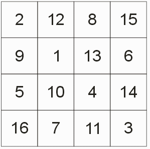
For dithering we use a lookup table. The table size is equivalent to the subpixel array size. So for a 4X super sample, the table size would be 4x4.

Figure 3 - a typical 4x4 dither matrix
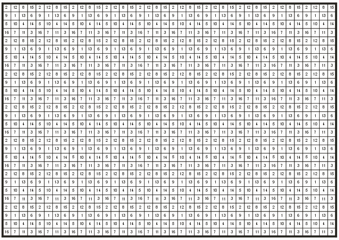
Now we tile our output bitmap space with the dither matrix as shown below.

Figure 4 - tiling the dither matrix over the raster window. The value at each pixel is the threshold.
Now at each location in this array, one counts the number of subpixels that are black. The total can range from 0 to 16. Then compare this total to the value at the pixel location.
IF [Array Total of sub pixels] >= [dither matrix value] THEN pixel is black (1)
ELSE pixel is white (0)
One can easily see the consequences of this dithering algorithm. If our output pixel is completely contained by a trace, then the total of the subpixels is always 16. Therefore according to our matrix, the output pixel is always black.
Figure 5: Output pixel completely inside of the trace.
If our output pixel is completely outside of the trace, then the total of subpixels is always 0 and our output pixel is always white.
Figure 5: Output pixel completely outside of the trace.
However if the output subpixel is on the edge of a trace the total of the subpixels will vary depending where the edge falls. Sometimes the output pixel will be set to 1; sometimes to 0. This varies depending not only on the number of subpixels but on where the output pixel falls in the matrix.
Figure 6: the output pixel crosses the edge of the trace.
The net effect is that pixels along the edge are effectively dithered.
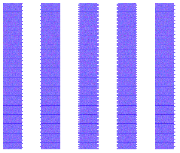
The exact nature of the dithering depends on the values one assigns to the dither matrix. An example of parallel equal width lines that have been dithered is shown below:

The computational costs of dithering are similar to that of grey scale output. First, the rasterizer must operate at 4X of the desired output DPI. This greatly increases the number of pixels that must be generated and then processed.
The the pixels must be "processed" to produce the final output. Artwork's dithering routines rely on muli-threaded operations in order to scale the throughput with the number of cores. Further, by subdividing the window into narrow stripes, we don't need to hold the entire results in memory - each stripe can be rasterized, dithered and then compressed (pack bits) in a small amount of memory space.
The argument to turn on dithering on the command line is -dither4.
-dither4
Setting the Dither Matrix Values
There are three options for setting the dither matrix values.
To use the default table don't put anything after your -dither4 option. The table below will be used:
| 1 | 12 | 7 | 15 |
| 9 | 2 | 13 | 8 |
| 5 | 10 | 3 | 14 |
| 16 | 6 | 11 | 4 |
To list the values on the command line use a comma separated list after the -dither4: argument.
-dither4:1,12,7,15,9,2,13,8,5,10,3,14,16,6,11,4
To get the values from a file called dither_matrix.txt use the @ sign followed by the path and file name of the text file.
"-dither4:@%CD%\dither_matrix.txt"
The file dither_matrix.txt can look like this:
1,12,7,15,    or   1 12  7 15  or  1,12,7,15,9,2,13,8,5,10,3,14,16,6,11,4
9,2,13,8,          9  2 13  8
5,10,3,14,         5 18  3 14
16,6,11,4         16  6 11  5
DPI
Remember, whatever DPI you specify on the command line will be divided by the dither setting. So if you set -dpi:20320 and you use -dither4 the output DPI will be 20320/4 = 5080.
Bitmap Compression
Because the dithered output is still monochromatic, you can specify -pack to get tiff output with packbits compression. Dithering reduces the compression ratio somewhat compared to the same file with no dithering.