Edge offset is the ability to take the original CAD data and to modify it by offsetting the edges of all regions either to swell each geometry or to shrink each geometry. Why? Sometimes this is to compensate in the opposite direction for changes induced by the process. Other times, the nature of the imaging causes changes to the ideal width of the lines and gaps.
We do our edge offset using Boolean geometric operations on the regions in the data. We do these Booleans prior to rasterization. The amount of computation is significant and applying the edge offset will slow down the total production of the bitmap.
An assumption is that the amount of offset is generally smaller than the smallest "feature" one finds in the source data. If the offset is not smaller one can lose features. Normally losing such features is not desirable or intended.
To produce an offset use the command line directive:
-shrink:O
where O = amount of each edge to offset.
The units of O are set by the -units: argument and are either in mm or inch -- no matter what the input units of the Gerber file.
A positive value of edge_offset i.e. shrink:0.010 reduces the size of the line width and increases the gap size between lines.
A negative value of edge_offset i.e. shrink:-0.010 increases the line width and reduces the gaps.
Example
We will use the sample file provided with the release and rasterize a small window at 5080 DPI (a 5 um pixel). We'll run it twice -- once with no shrink directive and once with a shrink of 0.010 mm. Then we will overlay the two bitmaps and compare them to see the difference.
gbr2greyscale.exe                      program to run
 icsxseed.gbr                          input file name
   -outname:icsx_pb_shrink_10um        output file name
      -outdir:%CD%                     output directory (CD=current directory)
        -workdir:%CD%                  working directory
           -window:0,90,250,140        data window to process
             -rotate:180               rotate by 180 degrees
               -unit:mm                use mm for units for shrink value
                -dpi:5080              set dots/inch = 5080 (5 um pixel)
                  -ram:256             use 256MB of RAM for image  buffer
                    -pack              output tiff with packbits
                       -shrink:-0.010  shrink data by 0.010 mm on all edges


The second command line is the same except that the outname is changed
and the -shrink: directive is removed.
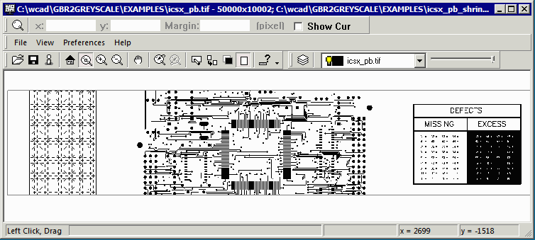
We can overlay the two bitmaps using Artwork's VLBV (Very Large Bitmap Viewer). When we first do that we don't see any visible difference.

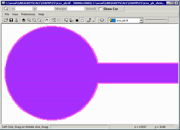
That's because the difference is quite small (two pixels on each edge.) So let's zoom in near a round pad and also change the colors of the two layers and apply some transparency.

Now the shrink of 0.010 mm is apparent. As a reference, the Gerber line width = 0.006 inch and the pad diameter is 0.030 inch.
or click https://vimeo.com/118969550 to view in maximum size.