

ASM 501 is a low cost but powerful DXF to Gerber translator intended to aid those who want to use AutoCAD (or other mechanical drafting programs) and need to create Gerber data for photoplotting.
Simple menus take you step by step through the translation process. Special functions help you assign blocks to flashes and set up draw apertures from polyline widths automatically.
Our powerful Gerber viewer, GBRVU, displays up to 48 layers simultaneously and lets you quickly verify your Gerber data before submitting your plot job.
ASM 501 outputs RS274X with embedded apertures which is supported by all modern photoplotters.
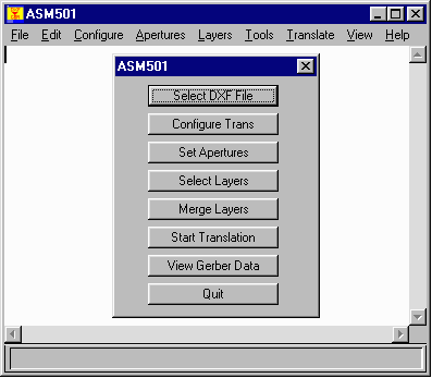
ASM 501/W is easy to use - the main button menu takes you step by step through the procedures to create Gerber data. Click each button and a dialog box opens. Fill in the settings (or accept the default settings) and move on to the next button.
The main menu (control dialog) takes the user through each step required to produce Gerber output from the DXF file.
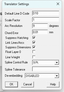
The user can configure ASM 501's behavior quickly and easily. ASM 501 remembers your settings in the .ini file so that after you have used the program once, you don't need to re-enter settings that never change.
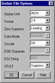
ASM 501W enables the user to control the RS274X output units, the precision format and the data mode as needed for your particular photoplotter.
In order to have a Gerber file you must define the apertures that the program will use. ASM 501 has an easy to use aperture menu.
Special function buttons include:
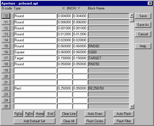
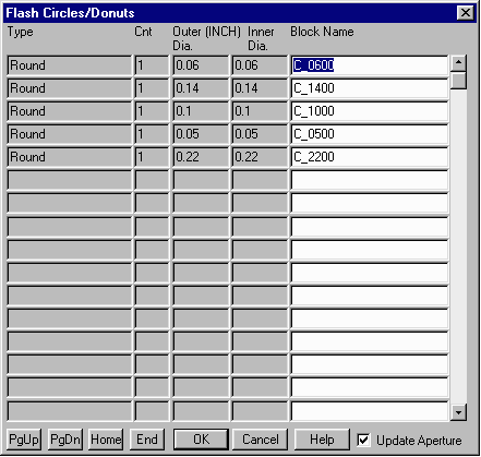
Some designers draw circuit pads using circles or donuts. ASM 501 can convert circles and donuts to flashes. It does this by scanning the file when you click on the Flash Circles button. It maps each unique circle diameter and donut size to a block name which can then be placed in the aperture list. The Flash Circles menu gives the designer full control of which circle and donut sizes are flashed.
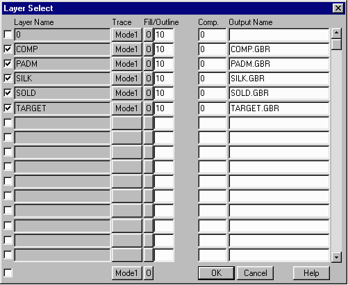
The Layer Select menu defines which layers to translate. You can control translation parameters layer by layer. Each DXF layer generates a corresponding Gerber file. You also can rename the Gerber output file if needed.
This application note gives you guidelines on how to setup and use AutoCAD to create good PCB layouts that will translate correctly with the ASM 500 family.