Copyright 2013-2017 , Artwork Conversion Software, Inc.
updated: August 17, 2017 for v2.42
updated: March 17, 2020
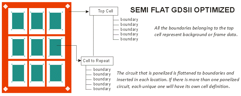
SFGEN is a preprocessor which reads either GDSII stream files or ODB++ printed circuit board manufacturing data files. It is designed to be used to produce an optimized GDSII file for Artwork's Real Time Correction RIP (RTCR). In order to get maximum throughput out of the RIP we rely on the fact that large panels or LCDs contain repetitive data.
The SFGEN program identifies such repetitive data and separates it from the background (or frame) data that is not repetitive. This enables the RIP to effectively place a large number of pixels using bitmap copy as opposed to rasterizing the entire panel by brute force. As the bitmap copy is much faster than re-rasterizing the same input data over and over again, the net result is faster rasterization.
The output of the SFGEN program is a GDSII stream file (no matter whether the input is GDSII or ODB++) and it has a limited hierarchy optimized so that the RIP need do as little rasterization as needed.
Start up SFGEN
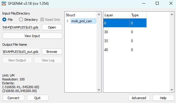
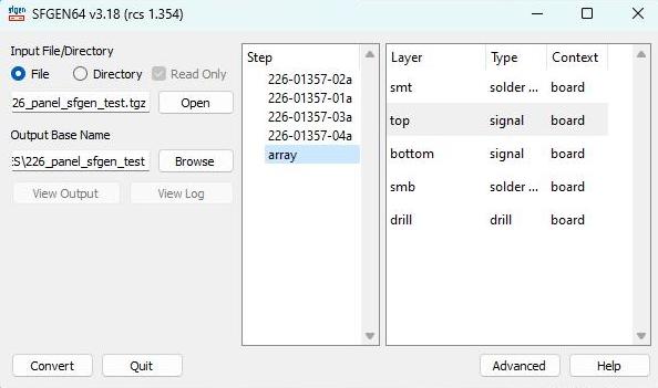
The main dialog will appear:
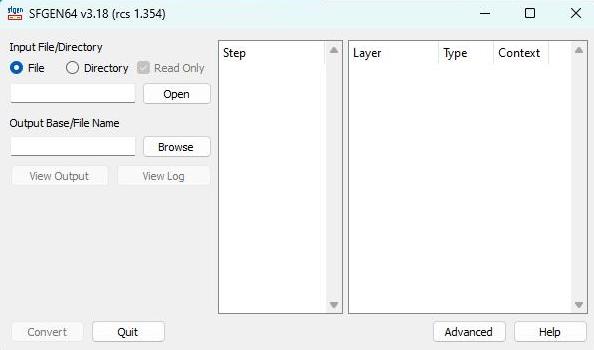
Input File/Directory
Use the Open button to select (open) either:
File - Select either a GDSII stream file or an ODB++ .tgz file.
Directory - Select the top level directory of an ODB++ hierarchy.
Read Only - if checked, SFGEN does not modify the contents of the input directory (for ODB++) and makes a copy. This may take more time if the ODB++ data is large.
Once you have selected the file, SFGEN will scan it, verify it is OK and will provide a list of Steps/Layers (for ODB++) or Cells/Layers (for GDSII) for you to select when running the conversion.
Output File/Base Name
Use the Browse button to select the location of the output stream file and its name.
Output Layer
Select the layer you want your data to appear on for the output GDSII file. If you don't select any particular layer it will defaul to layer 0. (Only applies for ODB++ input; for GDSII input it matches the selected input layer.)
Output Cell
Select the name of the top cell (structure) in your output GDSII file. If you do not make an entry it will default to TOP. (Only applies to ODB++ input; for GDSII input, the output cell matches the cell selected from the input.)
View Output
Once a file has been converted this button will go from gray text to black indicating it is active. Clicking on it will launch a GDSII viewer (specified in Advanced -> Settings) to display the output.
Step/Structure
This list box will show the available steps in the ODB++ file or the available structures in the GDSII file. You must select one of the steps/structures - typically the user will select the top level Step (often named panel or array) which contains references to arrays of circuit steps.
Layers
ODB++ and GDSII files generally contain many layers; however it is normal to rasterize only one of these layers per image. Therefore one should select the layer to process. If the user selects more than one layer:
a) for ODB++ input, only a single layer may be selected.
b) for GDSII input, the selected layers will be merged into a single output layer.
Convert
Clicking on the Convert button will start the conversion.
Advanced
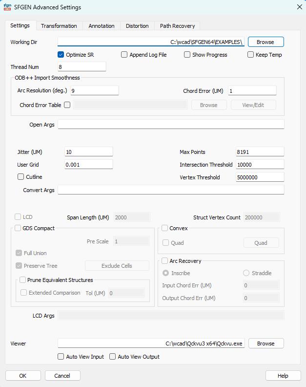
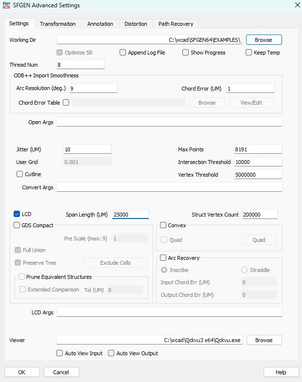
Clicking on the Advanced button will open a tabbed dialog enabling the user to control Settings, Transformation, Annotation and Distortion.
In the example below the user opened the ODB++ file called: 226.tgz and selected the step called "array" and selected the layer named "top".
User Grid
sets the grid for the output GDSII. Typical values are 0.001 or 0.01. Coarser grids may result in a loss of precision. Output GDSII file is always in units of microns no matter whether the input file is in inches or mm.
Jitter
a small tolerance (in um) used when testing whether output cells are identical or not. This is useful because the various explosions and union operations can create cell data that might be very slightly different - and in order not to generate a large number of almost identical cell definitions, the jitter parameter allows the program to treat all of them as a single cell.
Max Points
The maximum number of vertices per boundary in the output GDSII file. If a polygon will exceed this number it will be broken into two (or more) polygons so that the max vertex count is not exceeded.
Cutline
Instructs the program to use cut-lines instead of "butting" slices for polygons with islands. Do not use this option if you are also using the distortion function as it may result in illegal polygons in the output. This option is only present for testing purposes.
LCD mode makes certain assumptions about LCD layouts -- that the layout contains large structures and arrays. The program tries to re-factor these arrays to make them easier for a rasterizer to digest. The "span length" limits the dimensional size of the new cells that will be arrayed. If there is nested hierarchy inside the array, it is flattened and a new no-hierarchy cell is built for arraying - however the program makes sure that the flattened new cells do not exceed a maximum vertex count.
GDSCompact Flow and Parameters
The GDSCompact flow does not attempt to build a semi-flat file. Instead it focuses on reducing the nesting of the GDSII data to make it faster to process by certain rasterizers (not Artwork's rasterizer). It also breaks the polygons into quadrilaterals which are, by their nature, convex. Do not select this option if you have not consulted previously with Artwork concerning the type of rasterizer that will be used.
Convert Args
Command line arguments for the conversion engine are entered here. Normally this is left blank; the only time such arguments are needed is during testing and debugging.
Viewer
Enter the path and executable of a GDSII viewer. When clicking the View Output button, SFGEN will call this program passing the name of the GDSII output file.
Example: c:\wcad\qckvu3\qckvu3.exe
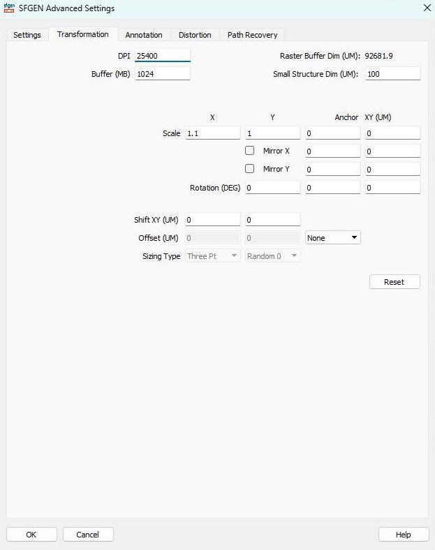
Transformation Tab DPI
Buffer Size
Enter the buffer size (this value is used in conjunction with the DPI) that the RIP will use to hold the repetitive data. This is not the raster buffer size but a separate buffer dedicated to holding the bitmap masters. Scale X>
Scale Y>
Mirror X>
Mirror Y>
Rotation>
Shift (X,Y)
Offset (Edge Bias)
Order of Transformation The transformations are performed in the following order:
all units are in microns except rotation which is in degrees |
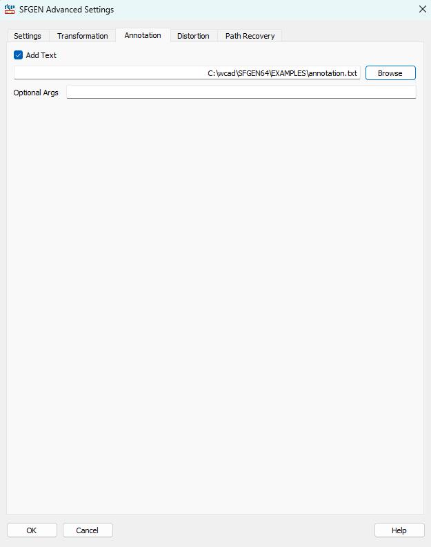
Annotation Tab
This tab enables the user to load an annotation file. The annotation file contains one or more annotation entries that instruct SFGEN to generate text (or to "annotate" the mask.) This text is usually some sort of an identification, lot stamp or date stamp associated with the actual writing of the mask. If the Add Text check box is selected, the user should also select an annotation file by using the Browse button. (Checking the box and failing to select a legal annotation file will cause a conversion failure ...) The annotation file can be created by hand, by an application or by a Qckvu3 plug-in. The syntax and details of the annotation file are here. |
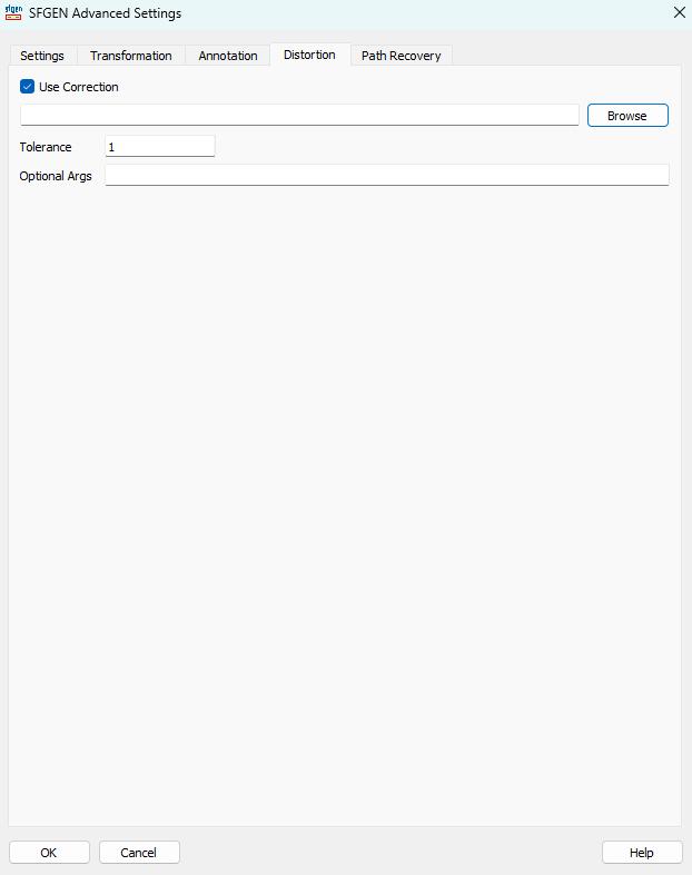
Distortion Tab
Distortion refers to a correction applied to the CAD data in order to warp the CAD data so that it "fits" on a substrate that may have been subject to some physical distortion due to either temperature or possibly processing (such as etching one side). Distortion can be corrected either in the SFGEN program or it can be corrected in the RTCR. The correction works by reading the coordinates in a table of common points from both the CAD data and the measured on the substrate. These points drive a correction engine that attempts to match the distortion found on the substrate. Of course, there is no guarantee that the distortion can be exactly matched from only a relatively small number of data points. See the reference section for details and examples. Use Correction File If checked, SFGEN will read the user specified correction file and apply corrections to the output file. Use the browse button to select the appropriate text file containing the coordinates. Tolerance A value (in microns) used to determine whether an instance of a cell is equivalent to other instances. If this value is set too small, each bitmap placement will require its own definition and the RIP will not run very quickly. See the reference section on distortion to understand how the tolerance affects repetition and RIP throughput. Optional Arguments Reserved for use by the developers during debugging. |
Path Recovery - Introduction
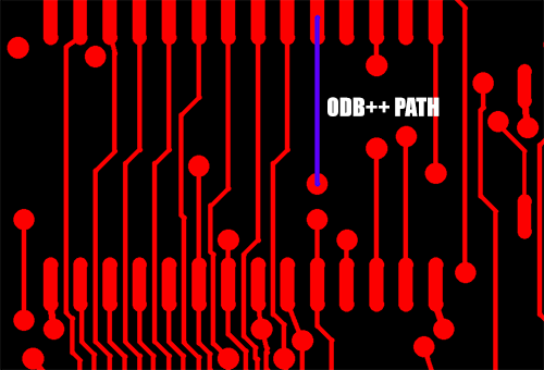
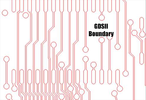
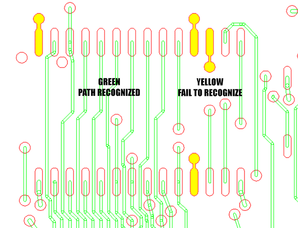
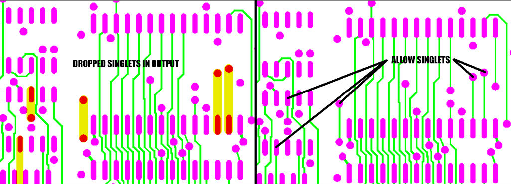
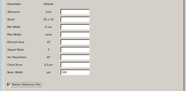
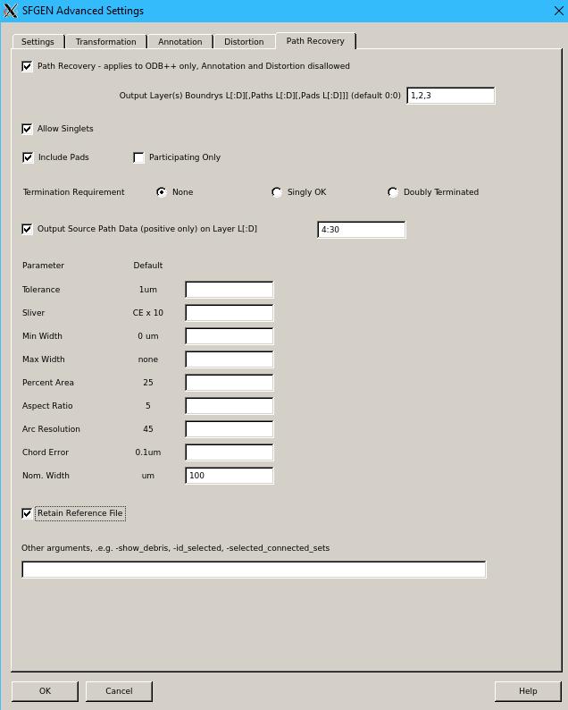
When SFGEN processes an ODB++ file, the circuit traces (aka lines or paths) are converted into GDSII boundaries due to the fact that the ODB++ data is run through Boolean operations during the conversion. So the output from a PCB (sample.tgz layer=top) consists solely of boundaries. The path recovery function examines each of the GDSII boundaries and tries to determine if it was originally a path connecting two pads in the source ODB++. If the identification is successful, then it will replace the boundary with a GDSII path (of the appropriate width) along with new boundaries representing the pads on either end of the path. There are some limitations -- not every pad/path combination in ODB++ can be identified reliably and converted back into a combination of boundary/path in GDSII. There are a number of tuning parameters when using Path Recovery that can affect which traces are recognized. Command Line UsageThe Path Recovery engine can be run from a command line but only on a GDSII file that was converted from ODB++ using SFGEN. You cannot use the engine directly on an arbitray GDSII file. For details on the command line syntax go to this page: Path Recovery DialogTo activate path recovery, press the Advanced button on the main menu which will take you to the tabbed Advanced Settings dialog; select the tab: Path Recovery. Then check the box next to Path Recovery. Controls and ParametersThe Path Recovery function includes a large number of controls and parameters that can be adjusted to "tune" the path recognition routine as well as to control the output. Output Layers, Boundaries, Paths Path Recovery produces a GDSII output which includes: paths (from traces/lines) pads (boundaries that have been recognized as pads) and boundaries (everything else). By default all three of these outputs are placed on layer 0:0 (where 0:0 indicates layer:datatype) However the user can specify the layer for each of the three groups by filling in the appropriate layer numbers. For example, if 10,20,30 is entered into the field for this control then: Boundaries : 10 Paths : 20 Pads : 30 Controlling What Gets Output from Path RecoveryDepending on the user's requirements, Path Recovery's output can be filtered. This section of the dialog window controls what gets output. Allow Singlets If "Allow Singlets" is checked, then a straight path connecting two pads will be passed to the output. Include Pads If "Include Pads" is checked, then any boundaries that are recognized as pads are output to the specified pad layer. Participating Only If "Participating Only" is checked, then only pads that terminate a path are output to the pads layer. Standalone pads are not output to the pad layer. Termination Requirement Choose one of the three path termination options: None If checked, then all paths are converted - even those that don't have a pad termination on either end of the path. Singly OK If checked, then paths that have either a single termination (or both sides terminated) are converted. Double Terminated If checked, only paths that have both ends terminated are converted. Output Source Path Data (positive only) on Layer L[:D] This is a debugging feature and is used if one needs to examine the boundaries that were the source for the path conversion. Most users have no need to check this. If you do check this make sure to specify a layer (or layer:datatype) that does not match any of the main outputs for boundaries, paths or pads. Parameter FieldsThe parameter fields can be used to "tune" the recognition of paths. However the actions of each parameter are fairly obtuse and in most cases adjusting these requires a deep understanding of both the program operation and the nature of your data. In most cases, the only parameter to adjust would be the "Nom. Width" by entering a value that is approximately the width of most of the paths one expects to recover. Tolerance
Defines a value in microns used for precision associated with general computations and vertex matching (default: 1um). Sliver
Specifies value for removing very thin data associated with boolean operations (default: 10 times chord error). Min Width
This option allows the user to set the minimum trace width. The program will ignore any path candidate with width lower than the value defined. Max Width
This option allows the user to set the maximum trace width. The program will ignore any path candidate with width greater than the value defined. Percent Area
A user defined value in percent used to not output candidate path data whose percent area relative to its extent box is greater than the value defined as path data (default is 25%). Aspect Ratio
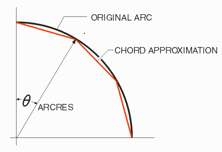
A user defined value where candidate path data whose length to width ratio is less than this value will be not be output as path data (default is 5). Arc Resolution and Chord Error Arc Resolution
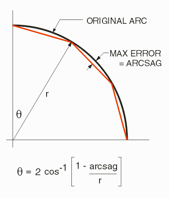
When converting from ODB++ to GDSII this controls how arcs and circles are broken into segments. Chord Error
When converting from ODB++ to GDSII this controls how arcs and circles are broken into segments. [This parameter was once called arcsag.] Nominal Width
Sets a value to be used by path recovery engine for automatic selection of conversion parameters. Value is in microns and should be set to a typical path width in the file. Retain Reference File
This option retains the reference input GDSII file created by SFGEN and passed to the path recovery engine. The reference file will derive its name from the output file with the trailing tag '_ref.gds'. Other Arguments
Allows the user to pass additional command line options to the path recovery engine. These include: |