 |
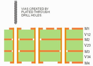
Importing Drill FilesMost designers output a drill file instead of a Gerber file for the vias. If the drill goes all the way through the board, then there is only one such file. 
In order to use the drill data, you first bring it into the DRILL2GBR utility, convert it to a Gerber file (with same format and units as the other Gerber files). When running NETEX-G you select this file (or files) in the Drill dialog and indicate what layers the drill passes through. On each conductor layer that the drill passes through a round piece of metal is generated that is the same diameter as the drill. If metal on that layer connects to the hole location (for example a pad or a solid ground plane) then a connection to that layer is made. If no metal touches the newly created round then no connection is made - however the round metal produced by the drill remains. |
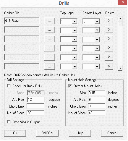
The Drill DialogIn order to define vias that connect different layers we use the drill data that is part of the board manufacturing data set. The drill file must first be converted into Gerber using the DRILL2GBR utility. The user then goes to the drill dialog to tell NETEX-G which file to load and which layers the drill passes through. Note: you should have first loaded the Gerber files for the board and defined the stackup prior to using this dialog. 
Gerber File - select the Gerber file (created from the drill data) to process. Check for Back Drills - A rarely used option for high speed boards that have drills from the back side of the board used to remove through via plating. Arc Resolution - Use this option to control how many sides for the drill cylinder. Chord Error - Another option to control how many sides for the drill cylinder. Number of sides - Another option to control how many sides for the drill cylinder. Drop Vias in Output - Use this option to simply ignore drill vias as they produce a lot of solid bodies and may not be needed. Detect Mount Holes - If you have mounting holes (typically unplated) check this box and specify a minimum size. You can see that more than one drill file is supported. This is intended to support designs with buried and blind vias. |
Download |
Benchmark Files |
Revision History |
Price |
|
|