 |
|
Related Topics: How Netex Sorts Gerber data into Wire Endpoints |
Importing Wire Bond DataWhile an IC package does not usually include wire bonds in the layout, the wirebonds connecting the die to the package are a critical path in modeling the electrical path from the die to the circuit board. NETEX-G can import wirebond data either from a Gerber file or from a ascii table. However because of 3D nature of wire bonds they cannot be treated exactly as just another conductor layer. Wire Bonds From Gerber DataSome package layout programs can output the wirebond layer as just another Gerber file. Several rules apply about how the Gerber data must be produced:
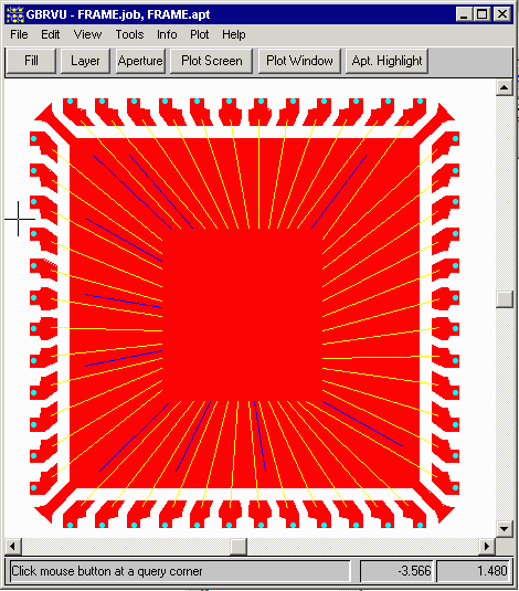
The screen shot of the Gerber files (as displayed in GBRVU) for a leadframe are shown below. 
|
| Gerber File | Color | Description/Comment |
| FRAME.GBR | RED | leadframe metal. This particular design was converted from an AutoCAD wire bond document used by the assembly house to Gerber using ASM 500. |
| WIRES.GBR | YELLOW | wires from bond attach point to die pad. This is a "draw" of diameter 0.025 mm. These were polylines in AutoCAD with width= 0.025 mm. |
| WIRES2.GBR | BLUE | wires from bond attach point to die pad. These are "down" bonds and were on a separate Gerber layer. |
| BALLPAD.GBR | CYAN | flash indicating the node or port where the Spice or S-parameter measurement will be made. (The spice model for each net will be calculated from the die side of the wire to the point on the package indicated by the small yellow ball pad.) These were added in AutoCAD to the leadframe drawing as the bond diagram normally doesn't include such information. They could have been added interactively in NETEX-G but it was much faster to array a circle on its own layer in AutoCAD and then flash them during the DXF to Gerber conversion. |
| If you would like to examine the Gerber data you can download the file frame48qfn.zip (15KB zipped). |
Download |
Benchmark Files |
Revision History |
Price |