

|
Step by Step Example - Drill GenerationWe will start with a simple STL file, plate.stl, that was created from a 3D model of a planar board that has several different sized holes "drilled" into it. Our objective is to get both the Gerber layout data and a drill file for the PCB manufacturer. 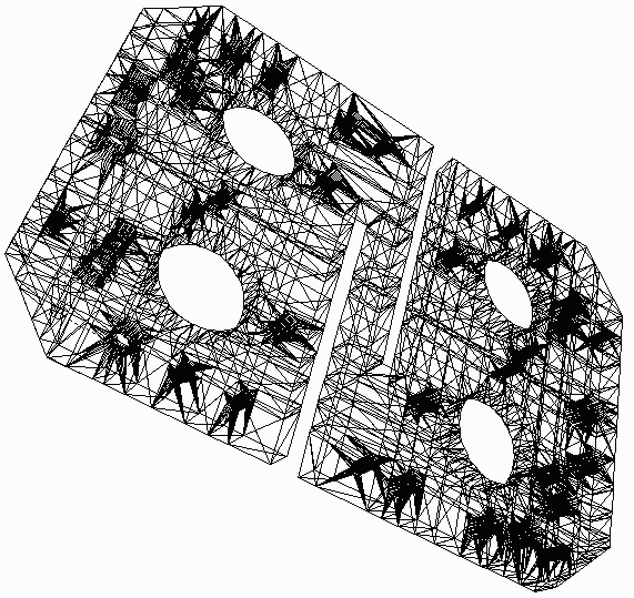
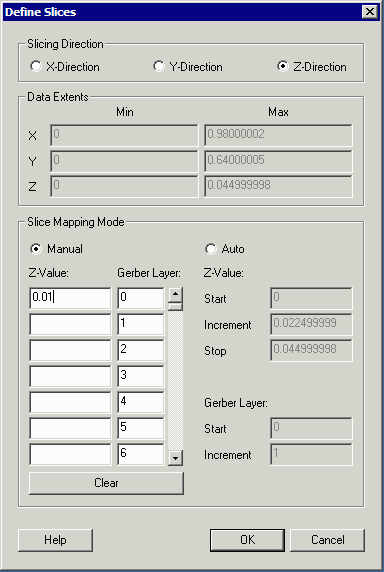
Since the design is uniform in Z, we need make only one cut. |
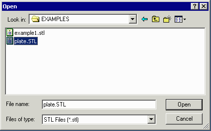
Opening the STL FileThe first step is to open the STL file to be converted. |
|
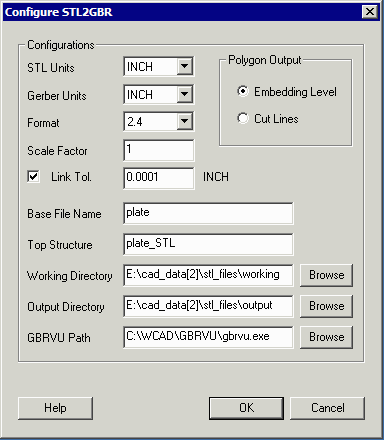 |
Configuring STL2GBRThe STL file was drawn in units of inches so we select inches as our units for both input and output. We select a Gerber format of 2.4 which will give us sufficient precision. The most important option (to get drill holes) is to select the Embedding Level option for the Polygon Output. |
Defining a Z SliceWe need to define at least one Z slice. Since this example part is uniform in z it does not matter where the slice is placed. Enter 0.01 (it is never a good idea to select 0 since there can be some numerical noise at the very top and bottom of the STL file.) Then click on OK. [Note - depending on your 3D MCAD settings, you may have to slice along the Y axis or even the X axis.] |
|
Running the Translation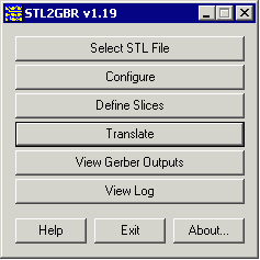
|
Now that the file is loaded, the translator configured and the z-slice defined, one only needs to run the translator by pressing the Translate button from the main menu. |
| Next Creating the Drill File using GBRVU |
| Details: 1 | 2 | 3 | 4 |
| Details | Download | Revision History | Price |