

|
Step by Step Example - Drill GenerationOpen the gerber file generated by STL2GBR using the GBRVU program. You should see the same layout as shown in the screen shot below: 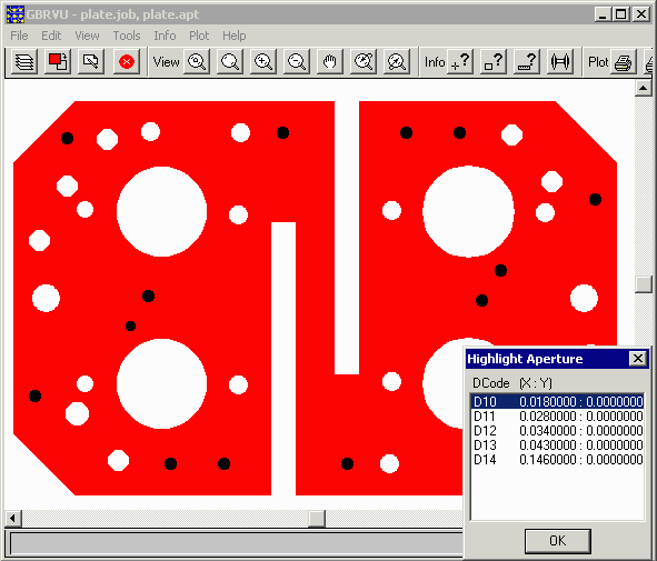
The holes are generated by flashes and are not contours. You can identify the flashes used for each hole with the Info | Highlight Apertures menu pick (or by pressing F2 on the keyboard) Double click on an aperture (such as D10) and all of the draw and or flashes using that aperture will be highlighted. |
Mapping Apertures to Drill ToolsEach of the different apertures in this Gerber file represent a different sized hole in the board. We want to map each aperture to its own drill tool in order to generate the drill file. 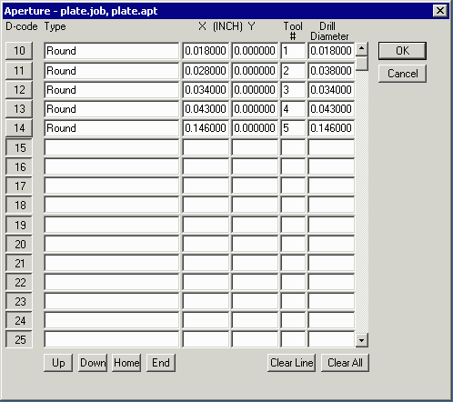
For each aperture assign a drill tool number (can be anywhere from 1-99) and set each drill tool to the same diameter as the corresponding aperture. If you do not want an aperture to represent a drill, then do not set a drill tool for it. |
Running Excellon Drill OutputTo create the Excellon drill file use the Tools | Drill | Excellon (Leading Zero Suppress) menu pick. 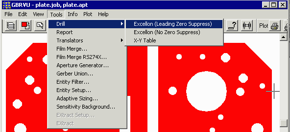
Each aperture is assigned a drill tool number (can be anywhere from 1-99) and each drill tool is set to the same diameter as the corresponding aperture. If you do not want an aperture to represent a drill, then do not set a drill tool for it. |
|
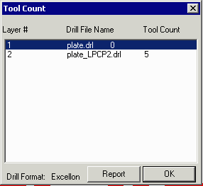
A small dialog will pop up summarizing the number of drill tools associated with each "layer." Note that the first layer (which contains the parent boundary) has no drills associated with it -- they are all in the second layer which has an extension LPCP2 where the LPC indicates this is a "clear" layer. Press OK to generate the output file. |
|
|
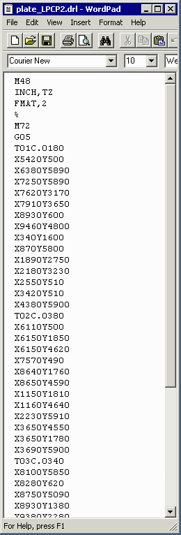
The Excellon Drill OutputThe Excellon Drill output is an ascii file of X,Y coordinates for each drill location. A header contains the format and units information. A tool select command (T) selects the tool and defines its diameter. This is the file that is sent along with the Gerber to the PCB manufacturer. |
| Details: 1 | 2 | 3 | 4 |
| Details | Download | Revision History | Price |