ODB++ RIP Raster ParametersThe ODB_RIP can support a wide range of raster devices through a set of parameters the calling application defines. DPI - Dots (pixels) per Inch. The calling program can specify the DPI as dots per inch, dots per mm or a pixel size in UM. Memory Buffers - the calling program can define the number of memory buffers and their size. This allows the rasterizer to break up a large high resolution image into multiple bands or stripes. When multiple memory buffers are used, the rasterizer can be filling one while the calling application is processing data on a different buffer. Number of Threads - the calling program can tell the library to use multiple threads (makes sense where there are multiple CPUs available.) Transformations - the calling program can apply the following transformations: shift, rotation, mirror and scale. Vertical or Horizontal Banding - the calling program can request that banding run vertically or horizontally. Golden Edge - the user can specify which edge is "golden" i.e. which vector edge will be aligned with the bitmap. The opposite edge will end up snapping to the nearest pixel. |
BandsThe ODB_RIP normally divides the image into bands. This allows one to process very large areas at high resolution without running out of memory. Bands can run horizontally or vertically as needed to match the machine's physical movements. The band's "width" is a function of the band's length, DPI and memory. The following equation gives the band width in terms of available memory: Example Your overall image size is 20 x 24 inches and you are ratsterizing (in vertical bands) at 5080 DPI. You allocated a buffer for the bitmap of 128 MB. How wide will a band be and how many bands are needed to cover the entire image? width = [128E6/8]/[24 x 5080 x 5080] = 0.0258 inch To cover the entire 20 inch width of the image one would need: number of bands = 20 / 0.0258 = 775.19 (776) Overriding Band SizeThere may be applications where the width of the band needs to precisely match the physical aspects of the imaging head. For example, the imaging head may be an array of 1024 LEDs so the width of the band must be exactly 1024. In this case it is possible to use the ODB_RipSetup argument: -bitmap_clip_dim:1024 |
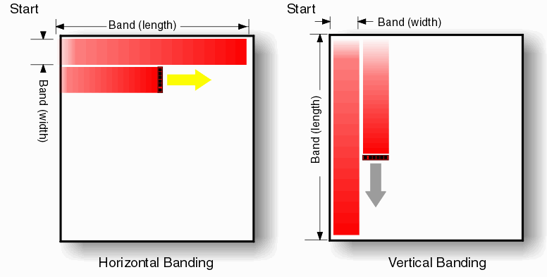
Memory BuffersAs the rasterizer converts the vector data into pixels, the bits are stored in the memory buffer. Once the process is completed the calling application can then access the buffer and do whatever operations are needed. If there is only a single memory buffer then the calling application must wait while the buffer is filled, and the rasterizer must wait until the callling program is done processing the filled buffer before the memory can be reused. For today's modern multi-processor systems this is inefficient. It is possible to direct the rasterizer to use two separate memory buffers. After the first band is completed, the rasterizer will start filling the second buffer. The calling program can be working on the first buffer while the rasterizer fills the second buffer. Depending on where the processing bottlenecks lie, this can greatly reduce total time to process a large image. Using two memory buffers does require additional RAM. |
Golden EdgeVector data will be "snapped" when it is rasterized to the nearest pixel. For example, if your DPI = 5080 then each pixel lies on a 5 um grid. If your application requires it you can designate one "edge" as the golden edge and the pixel data will be referenced to that edge. This is rarely needed but might be useful for some very critical applications. By default the top and left sides of the image (after any transformations) are automatically considered the golden edges. |
Download |
Frequently Asked Questions |
Revision History |
Price |