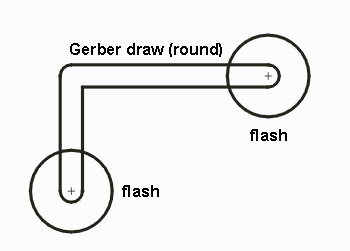
At left, a typical Gerber draw command (using a round aperture) connecting two round flashed pads. Circuit boards will have hundreds or thousands of geometries like this one.

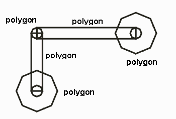
Prior to the Boolean operations to unionize the flashes and the draw, all elements have to be "fractured" so that they are polygons. The draw is assembled from rectangular sections and circles which simulate the dragging of a round aperture. There is a tradeoff between the number of vertices generated, the smoothness of the polygons and the precision of the reproduction of the input data.

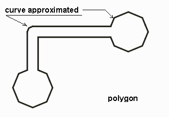
The polygons are fed to the Boolean module and the result is a single polygon contour of the original three objects. Of course, the results are not as smooth as the original data; the smoother and better approximation desired, the more vertices need to be used.
