| Sizing |
|
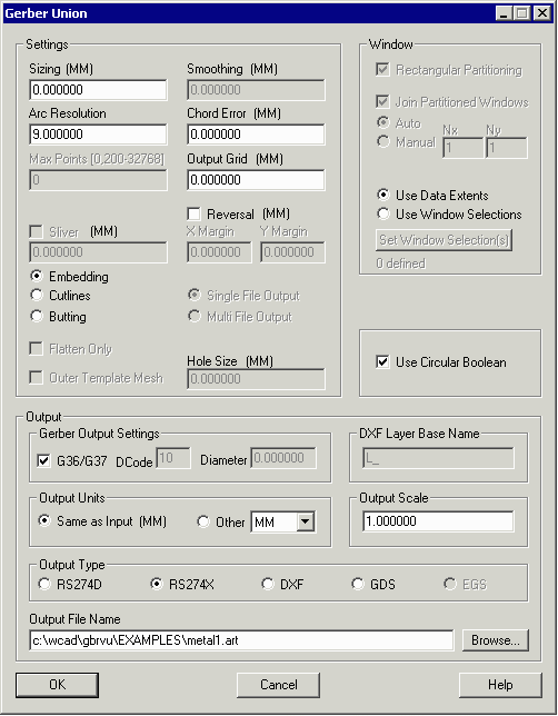
If not zero, sizes up or down the data. This is generally used for etch compensation. |
Arc Resolution |
|
if for some reason arcs cannot be preserved (currently this applies to aperture macros) this value tells GBRUnion how to fracture an arc by specifying the angle that each chord will subtend. Values range from about 2 degrees to 30 degrees. The lower the value the more vertices are generated and the smoother the approximation. |
Chord Error |
|
if for some reason arcs cannot be preserved (currently this applies to aperture macros) this value tells GBRUnion how to fracture an arc by specifying the maximum error between the center of the chord and the ideal arc. This parameter is more flexible than Arc Resolution since it takes into account the arc's radius. |
Output Grid |
|
This can be used to control the output resolution. Generally if not set, GBRUnion will attempt to create a more precise output grid than input grid in order to insure that no additional errors are produced by a degradation in grid resolution. |
|
|
|
Window |
|
Use Data Extents - GBRUnion calculates the extents of the input data and uses this calculated window. Use Window Selection - the user can define a data "window" either by manually entering the corner coordinates or by switching focus back to the viewing window and selecting one or more regions with the mouse. In this case, any data falling outside of the specified windows is clipped away during the boolean. |
|
|
|
Reversal |
|
it is possible to use GBRUnion's boolean to reverse the polarity of a layout. If checked, the user may enter a "margin" for both X and Y; without a margin the outer extents of the data come right up to the edge of the "enclosing rectangle" used to create the reversal. |
|
|
|
Embedding |
|
if clear islands are to be generated, produce them in the output using a parent outer figure and as many clear children figures as needed. This generally involves creating at least one additional layer for the clear figures (but could create more layers if needed) in both DXF and Gerber. |
Cutlines |
|
if clear islands are to be generated, produce them using a figure that contains one or more cutlines. This output can be used in both Gerber and DXF. However if one uses cutlines in DXF, such polylines cannot be extruded in Z --something to note if your intent is to add a Z thickness to a 2D DXF file. |
Butting |
|
if clear islands are to be generated, produce them using two or more figures butted up to surround the island area. This output can be used in both Gerber and DXF. |
|
|
|
Gerber Output - G37/G37 |
|
When specified all figures output in Gerber use the G36/G37 area fill command. No aperture (D-Code) need be assigned to the draw command. |
Output Units |
|
If not checked, the output file units match the input file units. Occasionally one needs to change units (for example, an input file in mm and the desired output file units in microns for GDSII applications.) If other is checked, then select an output unit from the drop down. |
Output Scale |
|
The default is 1. If set to some other value the output data is scaled up or down as specified. |
|
|
|
Output Type |
|
The radio buttons allow the user to specify one of the available output types: RS274D (older Gerber format), RS274X (modern Gerber format), DXF (AutoCAD's data exchange format) and GDSII (IC mask layout database). If an option is grayed out then it is not licensed for use. |
Output File Name |
|
Enables the user to set the path and output file name. |


