netex_title.gif


Assigning Nets and Node Labels

Gerber data does not contain any net names nor does it include any nodes or ports for the circuitry. The NETEX-G output is much more usable if critical nets and nodes have been labeled. There are several ways to get this information into NETEX-G; this page describes how to label nets and nodes interactively using the GBRVU program.

To add labels interactively, first make sure that you have loaded the Gerber files into the stackup since you will have to reference a stackup position. Then click on the Labels button to open the dialog. Click on the image below to start a 3 minute video tutorial.


Flash tutorial on assigning net labels using GBRVU


The Label Dialog Box

There are three tabs on the layer dialog box:

    Nets - label nets. You can place the label anywhere on the net.

    Nodes - label nodes. Consider these as test points on the circuit. They are usually placed at each "end" of the net. You need nodes in order to define the source/load when creating a Spice model.

    Padstacks - define a padstack. This function is for Ansoft ANF output and enables the Ansoft user to attach probe points. The padstack is associated to a node or port -- not to a net. The Ansoft field simulator attaches test points to padstacks.
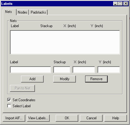
Netex-G Label Dialog Box

Adding a Net Label Manually

Suppose you know that a pin on your top layer at coordinate 5.25,6.50 is a VCC net. You could enter this information manually as follows:

In the label field type: VCC alm1.gif
In the stackup field type: 1 (top layer) alm2.gif
In the X(inch) field type 5.25 alm3.gif
In the Y(inch) filed type 6.50 alm4.gif
Click on the Add button. alm5.gif
The values are placed into the label window. alm6.gif


Page    [1]    2    3   


NETEX-G Page

Download

Benchmark Files

Revision History

Price