acad23di_web_page_logo.gif


Stacked Die Example

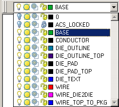
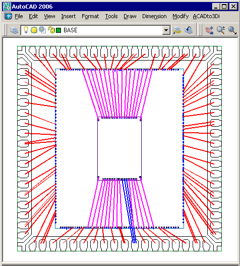
Our first example will be a stacked die on a QFN leadframe. The bond document was drawn using AutoCAD. A total of 9 layers are needed.

layer drop down


AutoCAD view of stacked die bond document.


Our Stackup

The substrate stackup is shown below. We have a solid base, then the lead frame conductor. The first DIE_OUTLINE will be used to create the die body and the DIE_PAD layer will form our die pads. The second die requires its own layers: DIE_OUTLINE_TOP and DIE_PADS_TOP.


substrate stackup


Wire Layers

Wires cannot be categorized as part of a stackup because they start on one layer and end on another. One must create as many wire layers as needed - each wire layer can be assigned its own starting and end level and its own wire model. In this example we have three wire layers to accommodate the different groups of starting and ending levels.
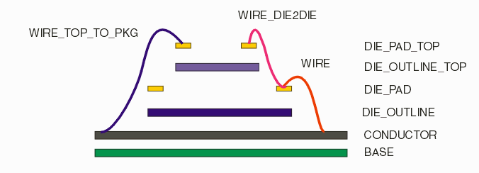

wire layer segregation

Now that we conceptually understand how our package and wires are organized, we can use ACADto3Di's dialogs to set the stackup order, the thickness and the wire profiles in order to build a 3D model of the package and wires.


More Info   1 | 2 | 3 | 4


  Drawing Rules Examples Download Price Revision History