Read3Di Web Page Header


Leadframe and IC drawn in AutoCAD

It is common to create documentation for wirebonding leadframes using AutoCAD. The leadframe layout is obtained from the manufacturer and the die outline and pads are imported from the GDSII data. lines are drawn representing wirebond from the die pad to the lead tip.

What if given such data, your job was to create a 3D model in Solidworks? How would you approach the problem?


LayoutGen

Artwork developed a special program, LayoutGen, specifically to take 2D data and extrude it in the Z plane into 3D data. In order to do this for leadframes LayoutGen has to do quite a lot of data preparation including:

Linking lines into closed polylines

Reversing the Polarity of the Data

Booleanizing data into legal shapes

Creating Z heights for each layer of data

Creating 3D wire profiles
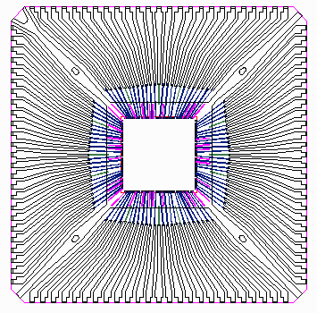
  leadframe example


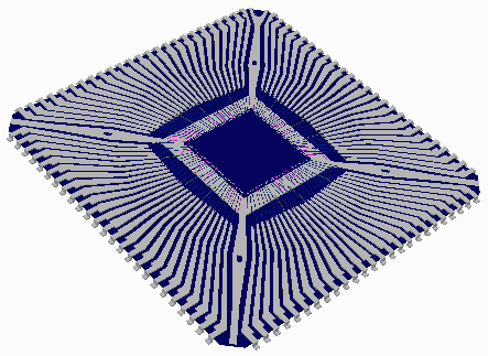
The output of LayoutGen is a 3Di file. We can visualize this 3Di file using our 3DVU program -- a snapshot is shown at right.

We can take the very same 3Di file and use it as input to Read3Di, a Solidworks plug-in, to import the data into SolidWorks.

  leadframe example


Importing into SolidWorks

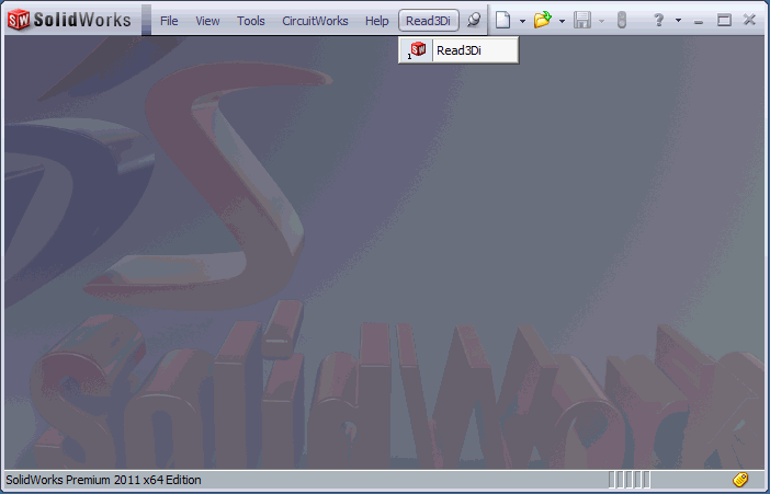
After installing the Read3Di add-in, just click on it to open the dialog inside of SolidWorks.

Read3Di Drop Down


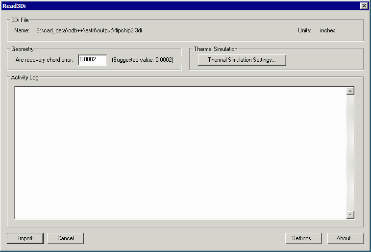
Select the file to import into SolidWorks and then hit Import.

  read3Di dialog


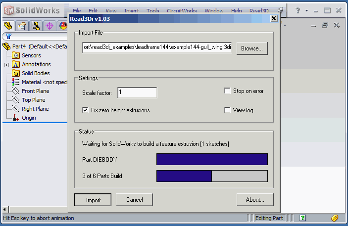
Read3Di will scan the 3Di file and then systematically import the collection of objects into SolidWorks. It creates a solid object for each element in 3Di and groups these into parts based on their input layer and input characteristics. Finally, it creates an assembly that references the parts.

This example took about 1 minute 20 seconds to run inside of SolidWorks 64 V11.


read3Di dialog


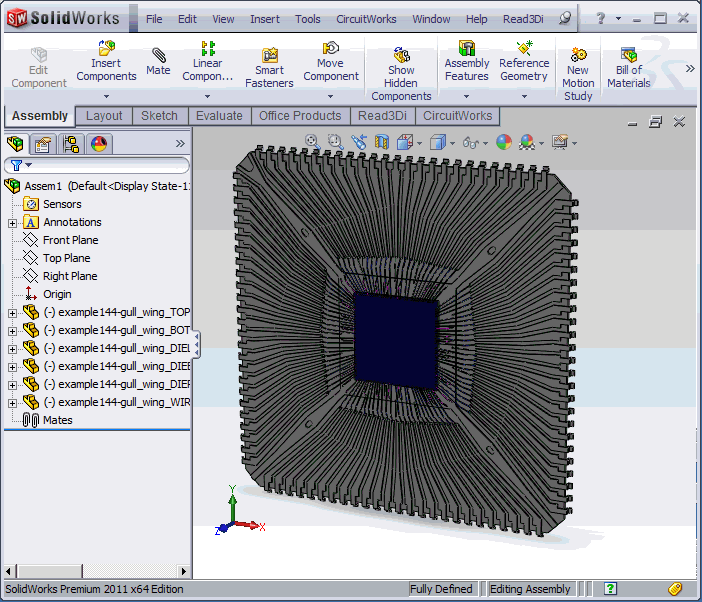
Upon completion you will see an assembly of parts in SolidWorks. You are now ready to do any 3D analysis that your project requires.


completed assembly in SolidWorks


Download Samples Video Tutorial Revision History Price