
The LayoutGen module runs inside of AutoCAD and takes a user step-by-step through the procedures necessary to organize a package layout so that it contains all the intelligence needed to import into APD/SIP.
The net result is a ULF (universal layout format) file that contains all of the necessary intelligent elements that APD requires for creating a database.
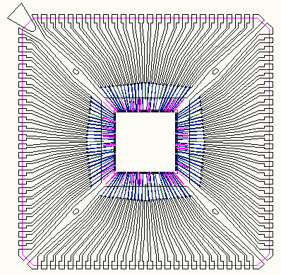
Lead frame drawn in AutoCAD with Die and Wires
LayoutGen takes you through the various steps needed to produce an intelligent database
New Project - defines the units and the layer cross section (needed by APD)
Line Linker - links geometries drawn with lines and arcs into closed figures.
Poly Reversal - clips and reverses lead frames that were drawn in reverse polarity.
Shape Builder - converts zero width closed polylines into shapes and supports voids.
Pin Builder - generates a pin at the end of each lead frame lead
Symbol Builder - creates the die symbol by scanning and package symbol
Wire Builder - identifies wires and determines to which die pad they are attached.
Wing Via - generates a via from the lead frame layer to the "bottom" which simulates the gull wing
Gull Wing Via - a more advanced and accurate model of the gull wing lead.
Net Builder - traces the connections between die pads, wires, shapes and package pads.
Export Layout - exports the results to the ULF database.
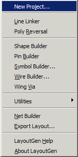
The LayoutGen Menu
In addition to the above functions, LayoutGen includes several utilities which are accessed from the Utilities... menu pick.
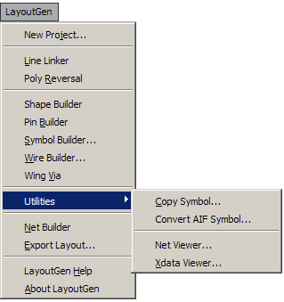
Some multi-chip designs use the same die and place it 2 or 3 or even 4 times. Copy symbol allows you to build the die symbol once, and then place additional copies of it as needed.
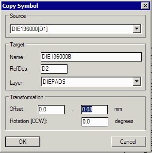
Notes
1) Although the symbol names in principle are the same you cannot assign them the same name; this is not a function that LayoutGen supports.
2) The transformation is relative to the coordinates of the source symbol - not to 0,0.
If you are working with a wirebond document that created the die symbol by importing an AIF file then this utility will automatically generate the die symbol for you. You only have to specify the layer that the die pads are placed on and the layer for the die outline. The die pad numbers and nets will be read from the block attributes on the die pads.
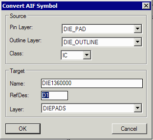
Pin Layer - the layer that the die pads are inserted onto.
Outline Layer - the layer that the die outline is drawn on
Class - for a die this should be IC
Name - the name of the symbol you want to create
Ref Des - the reference designator used for placement of this symbol
Layer - the APD Class/Subclass (not the AutoCAD layer) that the pins (die pads) belong to.
After net building you may wish to review elements to determine the nets that were correctly built. You can use this utility to click on the list of nets and see highlighted on the screen all elements of that net or you can click on a element on screen and see what net it belongs to.
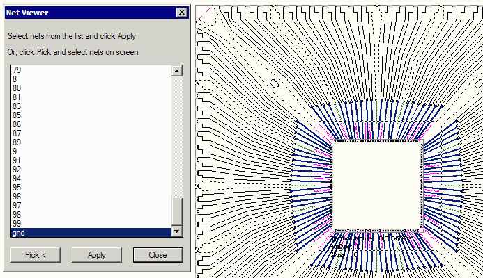
The net viewer can be either driven from the net list names or from the display.
This utility shows any extended data that has been created and attached to an AutoCAD entity by the LayoutGen program. There are different categories of extended data: object defines an entities object type, net defined an entity's net, parent defines a entities parent (for shapes), and so on. These hold the "intelligence" needed to create a valid APD database.
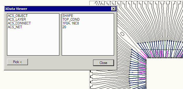
In this example the entity selected was a shape on layer (APD subclass) TOP_COND. It connects to entities with handles 1F01 and 16C8 and it belongs to net 20.