
|
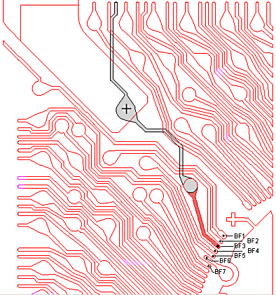
Example - PBGA In this example we are going to take the Gerber data from a two layer BGA and use it to show what the different extraction directives do. In the illustration above, you can see a quadrant of the BGA. Nodes - I started by first defining 7 nodes on the top (red) side of the BGA. These correspond to bond fingers 1-7 and are labeled BF1 ... BF7. On the bottom side of the board I labeled 7 nodes using the JEDEC nomenclature. You can see the node coordinates in the table below: B_NODES BF1 7.00 17.70 1 BF2 6.89 17.56 1 BF3 6.82 17.42 1 BF4 6.75 17.27 1 BF5 6.67 17.14 1 BF6 6.60 17.00 1 BF7 6.55 16.86 1 A1 2.23 23.26 3 B2 3.24 22.27 3 C3 4.24 21.26 3 D4 5.23 20.25 3 B1 2.23 22.27 3 G4 5.23 17.25 3 C2 3.24 21.26 3 E_NODES The 1 at the end of the first 7 lines indicates that NETEX-G should look on stackup layer 1 (the top layer) and the 3 indicates that NETEX-G should look on stackup layer 3 (the bottom of the board). This node information was entered into the NETEX-G dialog or it could have been pasted into the NETEX-G job file if you are running NETEX in batch mode. Net to Extract Our goal is to extract the net defined by the node BF3. (Let's suppose we wish to create a Spice model from the bond wire attach point to the ball pad on the bottom of the board.) To build an accurate model we need more than just the net in isolation. It is clear that this net will be influenced by the adjacent nets and also by conductors that pass under it and over it. The extract directive will enable us to get not only the net BF3 but also the surrounding metal that couples to that net.
|
|
Download |
Benchmark Files |
Revision History |
Price |