
|
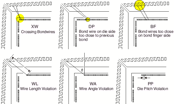
Wire DRCWirebondís DRC insures that each bond wire falls within the limits set by the assembly engineer. Each wire is checked for length, angle, and spacing. Any violations are reported in a summary file. Wirebond also reports the longest and shortest wires and identifies which finger or ring they are attached to. |

|

|
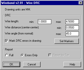
Setting up the DRC rules is simple. From the Wire DRC dialog the user defines the shortest allowable wire, the longest allowable wire, the spacing between wires (measured center-to-center) and the maximum angle measured normal from the edge of the die. The user also configures the error markers by setting the size, shape and color for each of the 6 different errors. |

|
|
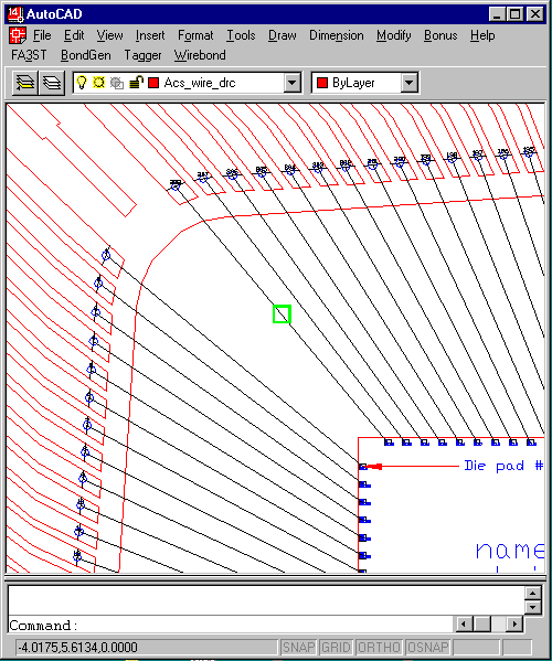
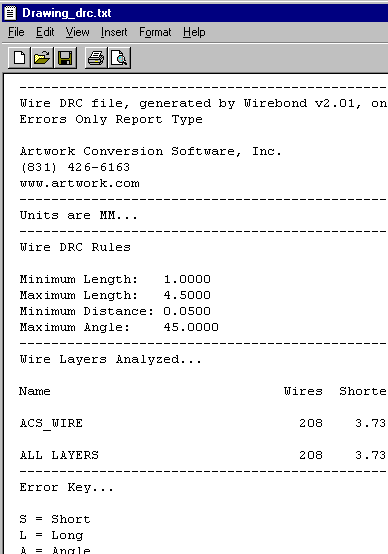
The Wire DRC module reports errors in two ways - graphically on the AutoCAD display (shown above) and as a text file (shown below). The assembly floor will feel much better about the wire diagram if you are able to attach a report to the drawing showing the DRC rules and the fact that no errors were found. |

|
| Page | 1 | 2 | 3 | 4 | 5 | 6 | 7 | 8 | 9 | 10 | 11 | |