 |
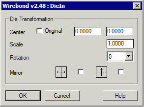
Placing the DieWirebond enables the designer to accurately place the die - either in the center of the package or offset by a specified amount. The designer can also rotate the die as it is placed in 90 degree increments. If required, the die can be mirrored and even scaled. For MCM designs with more than one die, each die is placed separately. The first step in placing the die is to have it prepared as an AIF file. If you imported it via GDSII, the Die Clean module created the AIF text file for you. However AIF can be easily created either from a spreadsheet or via other text based applications. | ||
|
Sample AIF Format DATABASE] TYPE=AIF VERSION=2.0 UNITS=MM [DIE] NAME=demo1 WIDTH=12.0000 HEIGHT=12.0000 [PADS] PAD1=SQUARE 0.0800 [NETLIST] ; NET DP# PAD DP-X DP-Y NET_208 208 PAD1 -5.5800 5.8800 NET_207 207 PAD1 -5.3600 5.8800 NET_206 206 PAD1 -5.1400 5.8800 NET_205 205 PAD1 -4.9200 5.8800 |
After loading the appropriate AIF file, a dialog will give you the placement options: 
|
|
|
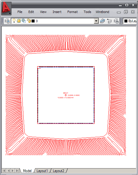
You can see that the die has been placed in the center of the package. The program is smart enough to autocenter the die, even if the die pad coordinates are not centered around 0,0. |

|
|
|